BT122 Data Sheet BT122 is a dual mode Bluetooth BR/EDR - BLE module targeted for applications that require both Bluetooth Low Energy and Classic connectivity. It can connect to legacy devices that only support Bluetooth SPP or Apple® iAP2 profiles as well to devices that support Bluetooth Low Energy. BT122 integrates a high performance Bluetooth radio, a low power ARM Cortex micro-controller and a Silicon Labs Dual Mode stack software.
Table of Contents 1. Feature List . . . . . . . . . . . . . . . . . . . . . . . . . . . . . . . . 4 2. Typical Applications . . . . . . . . . . . . . . . . . . . . . . . . . . . . 5 3. Design Guidelines . . . . . . . . . . . . . . . . . . . . . . . . . . . . . 6 3.1 PCB Layout Recommendations . . . . . . . . . . . . . . . . . . . . . . . . 6 3.2 Power Supply Recommendations. . . . . . . . . . . . . . . . . . . . . . . . 6 3.
11. Electrical Characteristics . . . . . . . . . . . . . . . . . . . . . . . . . 24 11.1 Absolute Maximum Ratings . . . . . . . . . . . . . . . . . . . . . . .24 11.2 Recommended Operating Conditions . . . . . . . . . . . . . . . . . . . . . .24 11.3 Logic Signal Characteristics 11.3.1 Digital I/O . . . . . 11.3.2 Reset . . . . . . 11.3.3 ADC . . . . . . . . . . . . . . . . . . . . . . . . . . . . . . . . . . . . . . . . . . . . . . . . . . . . . .
BT122 Data Sheet Feature List 1. Feature List • Bluetooth Features • Bluetooth v4.
BT122 Data Sheet Typical Applications 2. Typical Applications BT122 can be used in a wide variety of applications such as cable replacement, HID devices, health and fitness, PoS (point-of-sales), M2M connectivity, industrial and home automation gateways and others. silabs.com | Building a more connected world. Rev. 0.
BT122 Data Sheet Design Guidelines 3. Design Guidelines Certain hardware related design guidelines should always be followed when developing applications based on the BT122 module. 3.1 PCB Layout Recommendations • All ground pads should be connected to a ground plane. • The antenna layout should follow the example shown in the figure below and avoid the designs shown as crossed over.
BT122 Data Sheet Design Guidelines 3.4 Firmware Updating Related Recommendations To enable firmware updating an external UART interface connection as shown in Figure 3.2 Example: BT122 Firmware Update via UART Connections on page 7 is mandatory. BT122 firmware can be updated through the UART interface by holding the host MCU in reset state which typically will free the UART lines to be used by the update interface.
BT122 Data Sheet Pin-Out Description 4. Pin-Out Description This section contains a description of the BT122 pin-out. Each pin may have one or more functions which are all listed in tables. The pin-out is shown in the figure below GND 1 20 GND GND 2 19 GND GND 3 18 GND PA0 4 17 VDD PA1 5 16 RESET PC8 6 15 PF0 PC9 7 14 PF1 GND 8 13 GND 11 12 PF2 10 PF4 PF3 9 PF5 TOP VIEW Figure 4.1. BTT122 Pin-Out (Top View) 4.
BT122 Data Sheet Pin-Out Description 4.2 GPIO Pins General purpose I/O pins and their functions are listed below. Table 4.2. General Purpose I/O Pins and Their Functions Peripheral Function GPIO Name PA0 PA1 PC8 PC9 PF0 PF1 PF2 PF3 PF4 PF5 Pin Number 4 5 6 7 15 14 12 11 10 9 5V Tolerant N N Y Y Y Y Y Y Y Y CTS RTS RX TX UART I2C SCL SDA ADC Input ADC_CH0 ADC_CH1 Programming Interface silabs.com | Building a more connected world.
BT122 Data Sheet Power Control 5. Power Control 5.1 Power Supply Requirements BT122 is powered by a single power supply input (VDD). Nominal input voltage is 3.3 VDC and input voltage range 2.2 V to 3.6 V. If the module’s internal ADC functions are used minimum allowed power supply voltage is 2.4V. PA of BT122 is fully internally regulated. The VDD supply should be capable of supplying a peak current of at least 150 mA even though the average current consumption of BT122 will be much less than that.
BT122 Data Sheet Power Control 5.2.3 Wake-Up Pin Functionality This feature can be used to prevent to Bluetooth module from entering a sleep mode or alternatively can be used to wake it up from a sleep mode.
BT122 Data Sheet Interface 6. Interface 6.1 GPIO BT122 contains several pins which can be configured to operate as general-purpose digital I/Os, analog inputs, or to be used in combination with various built-in functions. The module contains I2C and UART communication. Most of pins (except PA0 and PA1) are 5V tolerant. All GPIO pins can drive current of up to ±50 mA. Any available GPIO signal can be assigned an interrupt function.
BT122 Data Sheet Antenna 7. Antenna 7.1 Measured Antenna Efficiency The measured antenna efficiency as a function of frequency is shown in the figure below. Efficiency (dB) Figure 7.1. Antenna Efficiency Related to Frequency silabs.com | Building a more connected world. Rev. 0.
BT122 Data Sheet Antenna The measured antenna Peak Gain as a function of frequency is shown in the figure below. Peak gain from plot is 2.1dBi. Peak Gain (dBi) Figure 7.2. Antenna Gain Related to Frequency silabs.com | Building a more connected world. Rev. 0.
BT122 Data Sheet Antenna The simulated impact to the operating range with different size of GND plane is shown in the figure below. Figure 7.3. Impact of the Size of GND Plane to Range of BT122 7.2 Measured 2D Radiation Patterns Typical radiation patterns of the BT122 module. 2D plots are shown be in Figure 7.4 Typical 2D Radiation Pattern for BT122, Phi 0 on page 16, Figure 7.5 Typical 2D Radiation Pattern for BT122, Phi 90 on page 17, and Figure 7.
BT122 Data Sheet Antenna Phi0 Gain Cut (dBi) Figure 7.4. Typical 2D Radiation Pattern for BT122, Phi 0 silabs.com | Building a more connected world. Rev. 0.
BT122 Data Sheet Antenna Phi90 Gain Cut Figure 7.5. Typical 2D Radiation Pattern for BT122, Phi 90 silabs.com | Building a more connected world. Rev. 0.
BT122 Data Sheet Antenna Theta90 Gain Cut Figure 7.6. Typical 2D Radiation Pattern for BT122, Theta 90 7.3 Measured 3D Radiation Patterns Typical radiation patters of the BT122 module. 3D plots are shown below. Figure 7.8 Typical 3D Radiation Pattern for BT122 on page 19 and Figure 7.8 Typical 3D Radiation Pattern for BT122 on page 19 represent radiation patterns from the module on 2440MHz frequency. silabs.com | Building a more connected world. Rev. 0.
BT122 Data Sheet Antenna 3D Gain Patter @ 2440MHz, View 1 Figure 7.7. Typical 3D Radiation Pattern for BT122 3D Gain Pattern @ 2440MHz, View 2 Figure 7.8. Typical 3D Radiation Pattern for BT122 silabs.com | Building a more connected world. Rev. 0.
BT122 Data Sheet Bluetooth® Software Stack 8. Bluetooth® Software Stack The software implements a full Bluetooth BR/EDR and LE compatible Bluetooth Stack and L2CAP, RFCOMM, SMP, and ATT protocols as well as Bluetooth SPP, HID, Apple iAP2, GATT over BT profiles and any GATT-based Bluetooth Low Energy profile.
BT122 Data Sheet Host Interface 9. Host Interface 9.1 UART For applications where an external host (such as an MCU) is used, BT122 can be controlled over the UART interface using the BGAPI™ serial protocol. For stable UART communication, it is recommended to use hardware flow control (RTS/CTS pin). It is also recommended that the accuracy of the clock of the controlling host should be 1% or better for the UART signaling to work reliably with speeds exceeding 115200 kbps (maximum baud rate is 3 Mbps).
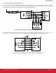
BT122 Data Sheet Connection Examples 10. Connection Examples The following sections show how to connect the BT122 Dual Mode Module with various external devices using the UART and I2C interface. 10.1 Connecting an External Host Using the UART Interface The connection to an external host is done using the UART interface of the module.
BT122 Data Sheet Connection Examples 10.2 Connecting an External Device Using I2C Interface The BT122 Dual Mode Module contains one physical I2C peripheral. Pin configurations for the I2C interface are listed in Table 4.2 General Purpose I/O Pins and Their Functions on page 9. An example of this type of interfacing is shown in the figure below. Note the pull-up resistors on the SDA and SCL lines.
BT122 Data Sheet Electrical Characteristics 11. Electrical Characteristics 11.1 Absolute Maximum Ratings Table 11.1. Absolute Maximum Ratings Parameter Min Max Unit Storage temperature -40 85 °C 0 3.6 V 5V tolerant GPIO voltages -0.3 5.25 V Other terminal voltages -0.3 VDD+0.3 V Output current sourced or sunk by any GPIO pad 50 mA Current on all GPIO pads combined 200 mA VDD 11.2 Recommended Operating Conditions Table 11.2.
BT122 Data Sheet Electrical Characteristics 11.3.2 Reset Table 11.4. Reset Pin Characteristics Power-on Reset Power-on reset threshold (rising edge) RESET signal pulse width (pulled low) Min Typ Max Unit - 1.2 - V TBD - - ms 11.3.3 ADC Table 11.5. ADC Pin Characteristics ADC Characteristics Min Typ Max Unit ADC input voltage range 0 - VDD V ADC integral nonlinearity error, end point method, 12-bit -6 - 6 LSB ADC offset error -3 0.25 3 LSB ADC gain error - -0.
BT122 Data Sheet Electrical Characteristics 11.4 Power Consumption Table 11.6. Typical Power Consumption of Different Operating States Operation State Current Unit Description Power Saving Mode 1 - RF idle 6.6 mA CPU idle RF idle Power Saving Mode 2 - RF idle 89 µA CPU sleep RF idle 1 - 10 mA Reset-signal held low 72.6 mA +11dBm, CPU active 61 mA +5dBm, CPU active Reset state Continuous transmission - BDR Continuous transmission - EDR Table 11.7.
BT122 Data Sheet RF Characteristics 12. RF Characteristics Table 12.1. Supported Frequencies and Channels Parameter Min Max Unit Frequency 2402 2480 MHz Channels BR/EDR 0 78 CH# Channels BLE 0 39 CH# Note: According to the Bluetooth standard, Classic BR/EDR uses frequency hopping across 79 channels, 1 MHz apart. BLE uses frequency hopping across 40 channels, 2 MHz apart. Table 12.2. Typical Reciever Sensitivity Packet Type -40 to 85°C Unit DH1 -94 dBm 2DH1 -95 dBm 3DH3 -89.
BT122 Data Sheet Packaging Specifications 13. Packaging Specifications 13.1 Dimensions Figure 13.1. BT122 Packaging Specifications silabs.com | Building a more connected world. Rev. 0.
BT122 Data Sheet Packaging Specifications 13.2 PCB Landing Pattern Figure 13.2. BT122 PCB Land Pattern silabs.com | Building a more connected world. Rev. 0.
BT122 Data Sheet Packaging Specifications 13.3 Package Marking Figure 13.3.
BT122 Data Sheet Soldering Recommendations 14. Soldering Recommendations It is recommended that final PCB assembly of the BT122 follows the industry standard as identified by the Institute for Printed Circuits (IPC). This product is assembled in compliance with the J-STD-001 requirements and the guidelines of IPC-AJ-820. Surface mounting of this product by the end user is recommended to follow IPC-A-610 to meet or exceed class 2 requirements.
BT122 Data Sheet Tape and Reel Packaging 15. Tape and Reel Packaging This section contains information regarding the tape and reel packaging and materials of packaging with dimensions for the Bluetooth Dual Mode BR/EDR and BLE BT122 module. 15.1 Reel Material and Dimensions Figure 15.1. Reel Dimensions silabs.com | Building a more connected world. Rev. 0.
BT122 Data Sheet Tape and Reel Packaging 15.2 Tape Material and Dimensions Figure 15.2. Tape Dimensions silabs.com | Building a more connected world. Rev. 0.
BT122 Data Sheet Certifications 16. Certifications This section details the regulatory certification status of the module in various regions. The address for the module manufacturer and certification applicant is: SILICON LABORATORIES FINLAND OY Alberga Business Park, Bertel Jungin aukio 3, 02600 Espoo, Finland The BT122 modules have the brand name of “Silicon Labs”.
BT122 Data Sheet Certifications OEM Responsibilities to comply with FCC Regulations This module has been tested for compliance to FCC Part 15. OEM integrators are responsible for testing their end-product for any additional compliance requirements needed with this module installed (for example, digital device emissions, PC peripheral requirements, etc.).
BT122 Data Sheet Certifications Class B Device Notice Note: This equipment has been tested and found to comply with the limits for a Class B digital device, pursuant to part 15 of the FCC Rules. These limits are designed to provide reasonable protection against harmful interference in a residential installation. This equipment generates, uses, and can radiate radio frequency energy and, if not installed and used in accordance with the instructions, may cause harmful interference to radio communications.
BT122 Data Sheet Certifications CAN ICES-003 (B) This Class B digital apparatus complies with Canadian ICES-003. ISED (Français) Le présent émetteur radio (IC: 5123A-BT122) a été approuvé par Innovation, Sciences et Développement Économique Canada (ISED Canada, anciennement Industrie Canada) pour fonctionner avec l'antenne intégrée, avec le gain maximal admissible indiqué.
BT122 Data Sheet Certifications 16.4 Proximity to Human Body When using the module in an application where the radio is located close to the human body, the human RF exposure must be taken into account. FCC, ISED, and CE all have different standards and rules for evaluating the RF exposure.
BT122 Data Sheet Certifications 16.5 Japan - MIC The BT122-A modules are certified in Japan with certification number 209-J00442. Since September 1, 2014 it is allowed (and highly recommended) that a manufacturer who integrates a radio module in their host equipment places the certification mark and certification number on the outside of the host equipment. This combination of mark and number, and their relative placement, is depicted in figure Figure 16.
BT122 Data Sheet Certifications 16.6 South Korea - KC The BT122 modules have a RF registration for import and use in South-Korea. Registration number is: R-R-BGT-BT122 The RF-certified module is meant to be integrated into an end-product, which is then exempted from doing the RF emission testing, as long as the recommended design guidance is followed.
BT122 Data Sheet Ordering Guide 17. Ordering Guide Ordering Code Description Packaging BT122-A-V2 BT122 Bluetooth dual mode BR/EDR - BLE module with an integrated antenna. Cut tape BT122-A-V2R BT122 Bluetooth dual mode BR/EDR - BLE module with an integrated antenna. Reel Note: Throughout this document, the devices in the table above may be referred to by their product family name (BT122), model name (BT122-A), or full ordering code. silabs.com | Building a more connected world. Rev. 0.
BT122 Data Sheet Revision History 18. Revision History Revision 0.6 June 2021 • Updated Table 16.1 Minimum Separation Distances for SAR Evaluation Exemption on page 38 • Updated China - SRRC Revision 0.51 June 2021 • Updated Feature List: EDR updated to +5dBm • Updated ISED French text • Added Declaration ID, Qulification Design ID, and listing date in Section 16.8 Bluetooth Qualification • Updated text and Figure cross-reference in Section 16.5 Japan - MIC Revision 0.
Smart. Connected. Energy-Friendly. IoT Portfolio www.silabs.com/products Quality www.silabs.com/quality Support & Community www.silabs.com/community Disclaimer Silicon Labs intends to provide customers with the latest, accurate, and in-depth documentation of all peripherals and modules available for system and software implementers using or intending to use the Silicon Labs products.