LANGUAGE DESCRIPTION DE BETRIEBSANLEITUNG EN OPERATING INSTRUCTIONS FR MANUEL D’INSTRUCTION IT ISTRUZIONI OPERATIVE ES INSTRUCCIONES DE OPERACIÓN Manual Version V01.00-REV01.
TP-R-400 Table of Contents Table of Contents 1 Description .......................................................................................................................................................... 5 1.1 1.1.1 Preface .......................................................................................................................................... 5 1.1.2 Safety Instructions ........................................................................................................
Table of Contents 4 TP-R-400 2.2.5 Aligning Stylus to Spindle Centre ................................................................................................. 28 2.2.6 Adjusting the touch probe in the tool holder with a 90° adapter.................................................... 29 2.3 Optical Status Display............................................................................................................................... 30 2.4 Replacing Measuring Unit .....................
TP-R-400 1 Description Description 1.1 General 1.1.1 Preface The safety instructions in this manual have to be strictly observed to guarantee a safe and reliable function of the touch probe and to avoid personal and material damage. The meaning of the symbols related to the safety instructions is described in the table below: NOTICE INFORMATION 1.1.2 NOTICE indicates important information that, if not observed, could lead to property damage/malfunctions.
Description 1.2 TP-R-400 Purpose The radio-wave touch probe TP-R-400 is used for workpiece measurement, and automatic determination and compensation of deviating angular positions of workpieces. Moreover, it is used for setting zero points inside the machine tool. The radio-wave touch probe TP-R-400 is capable of measuring workpiece geometries, like edges, bores, pins, slots, webs, angles, corners and circular arches.
TP-R-400 1.3 Description Declarations and Approvals 1.3.1 Europe and UK (EU and UKCA Declaration of Conformity) The EU and UKCA Declarations of Conformity can be found at the end of these operating instructions. If required, a copy of the signed original declarations of conformity may be requested from the address given on the back cover. 1.3.2 USA (FCC Declaration) This device complies with Part 15 of the FCC.
Description 1.4 TP-R-400 System Components m&h Radio-wave Touch Probe TP-R-400 m&h Radio-wave Receiver RWR95.51 m&h Radio-wave Receiver RC-R-100 Measuring unit MY21.00 Precision measuring unit HPP44.10 Measuring unit PP41.
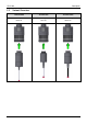
TP-R-400 1.5 Description Variant Overview TP-R-400-MY# TP-R-400-PP# TP-R-400-HPP# Measuring unit Measuring unit Precision measuring unit MY21.00 PP41.00 HPP44.
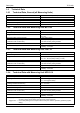
Description 1.6 1.6.1 Technical Data Technical Data, General (all Measuring Units) Transmission frequency Transmission/reception range Power supply Material Temperature range Sealing 1.6.2 Recommended Probing Feedrate Unidirectional Repeatability (deflection from one direction) Weight TP-R-400-MY without tool holder Maximum Battery Life with Lithium Battery ±X; ±Y; -Z XY = ±14°; Z = -4.5 mm XY = 1 N Z=6N max. 2000 mm/min max. 1 µm (2 Sigma) with 50 mm stylus and 254 mm/min probing feedrate approx.
TP-R-400 1.7 1.7.1 Description Dimensions Dimensions with Measuring Unit MY21.00 Customer specified tool holder Aligning stylus to spindle centre Battery compartment, Display, Setting button Measuring unit MY21.00 Stylus Dimensions with Measuring Unit MY21.00 INFORMATION The dimension X for the length of the tool holder, required to calculate the total length L of the probe system, can be found in the accessories catalogue. The total length L is the sum of the probe length and the dimension X.
Description 1.7.2 TP-R-400 Dimensions with Measuring Unit PP41.00 Customer specified tool holder Aligning stylus to spindle centre Battery compartment, Display, Setting button Measuring unit PP41.00 Stylus Dimensions with Measuring Unit PP41.00 INFORMATION The dimension X for the length of the tool holder, required to calculate the total length L of the probe system, can be found in the accessories catalogue. The total length L is the sum of the probe length and the dimension X.
TP-R-400 1.7.3 Description Dimensions with Precision Measuring Unit HPP41.10 Customer specified tool holder Aligning stylus to spindle centre Battery compartment, Display, Setting button Measuring unit PP41.00 Stylus Dimensions with Measuring Unit HPP41.10 INFORMATION The dimension X for the length of the tool holder, required to calculate the total length L of the probe system, can be found in the accessories catalogue. The total length L is the sum of the probe length and the dimension X.
Description 1.8 TP-R-400 Transmission and Reception Area INFORMATION The transmission/reception ranges shown below only apply under optimum operating conditions. For a secure signal transmission probe and receiver must be located in the transmission area of the other device. The range for a secure signal transmission is up to 18 m. 0…1 ≙ 0%...
TP-R-400 1.9 1.9.1 Description Delivery Contents, Accessories and Spares Delivery Contents INFORMATION A complete order number must contain at least the number of the touch probe and the description of the measuring unit (refer to chapter 1.5) (e.g. TP-R-400-PP). Order Number Description TP-R-400-MM# Radio-wave Touch Probe TP-R-400 MM = Measuring unit 1.9.2 Styli A variety of different styli, extensions and stylus adapters are available for m&h touch probes.
Description 1.9.4 TP-R-400 Accessories, General Order Number Description 91.00-SWV-XX (on request) Air jet with swivel screw fitting D20-VDI-90 Angle adapter for tool holder VDI D20-MO-B Modular adapter D20/D28 (Ø20/Ø28) 41.00-PP# Measuring unit PP41.00 41.10-HPP# Precision measuring unit HPP41.10 21.00-MY# Measuring unit MY21.00 41.00-KA Cross adapter 41.00-KA-V Screw plug for cross adapter 21.00-VE30 Extension (L=30 mm/1.18") 21.00-VE50 Extension (L=50 mm/1.97") 41.
TP-R-400 1.9.5 Description Spares Order Number Description 4316 Battery (3.6 V, ½ AA) 40.02BATTERIEDECKEL Battery cover 5764 Battery cover lock 5186 20x1 Viton O-ring for battery cover 1351 Clamping screw M5x0.5x7 (AF2.
Operation 2 TP-R-400 Operation 2.1 Tools, Measurement and Test Equipment Order Number Description 0227 Hexagon key AF1.3 mm 1097 Hexagon key AF2 mm 1346 Hexagon key AF2.5 mm 1780 Hexagon key AF3 mm 3489 Hexagon key AF4 mm 5840 Assembly key for battery cover 1665 Spanner AF4 mm 0885 Mounting pin 2951 C-spanner 3079 Dial gauge TP-R-400-TB Tool box, consisting of: 2x Battery (3.
TP-R-400 2.2 Operation Commissioning and Setup of the Touch Probe 2.2.1 2.2.1.1 Installing/Changing the Stylus Installing/Changing the Stylus (Measuring Unit MY21.00) NOTICE Risk of damage to the equipment! • • 1. Do not apply any turning force to the measuring unit! During replacement, always hold the stylus connection with the spanner AF4 mm! Unscrew the stylus from the touch probe using the mounting pin. 1. Carefully screw the new stylus with mounting pin into the touch probe (Fig. 6). 2.
Operation 2.2.1.2 TP-R-400 Installing/Changing the Stylus (Measuring Unit PP41.00/HPP41.10) NOTICE Risk of damage to the equipment! The probe mechanic is sensitive, therefore never use excessive force when screwing in the stylus! • • • 1. The screwing torque is M=2 Nm! When using a break shaft adapter (91.00-S-M4/M4), only screw in the stylus with a maximal torque of 1 Nm (0.74 lbf.ft)! The use of a break shaft adapter (91.00-S-M4/M4) is not permitted in conjunction with precision measuring unit HPP41.
TP-R-400 2.2.2 2.2.2.1 1. 2. Operation Mounting/dismounting the tool holder Mounting tool holders Ø20 Dismounting the tool holder: 1.1 Remove all "A" and "C" screws (refer to Fig. 8). 1.2 Remove tool holder Mounting the tool holder: 2.1 Carefully slide the tool holder onto the probe body, adjusting thread "C" to the cone holes on the probe. 2.2 Insert both clamping screws "C" and tighten lightly. 2.3 Insert all adjustment screws "A" and tighten lightly. 3.
Operation 2.2.2.2 1. 2. TP-R-400 Mounting tool holders Ø28 Dismounting the tool holder: 1.1 Remove clamping screws from the tool holder. 1.2 Remove tool holder. 1.3 Remove all "A" and "C" screws from the modular adapter (refer to Fig. 9). 1.4 Remove modular adapter from touch probe. Mounting the tool holder: 2.1 Carefully slide the modular adapter onto the probe body. Align the „C“ threads with the conical bores. 2.2 Insert both clamping screws „C“ and tighten lightly. 2.
TP-R-400 2.2.3 Operation Inserting/Changing the Battery NOTICE Risk of damage to the equipment! • • • Clean and dry the probe well before opening! Do not use compressed air to clean the touch probe! Replace empty batteries immediately! 1. Turn battery cover lock anti-clockwise and remove the battery cover to the outside of the housing of the touch probe. 2. Remove the used batteries.
Operation 2.2.4 2.2.4.
TP-R-400 Operation To access the touch probe menu, press the button on the back of the touch probe for approx. 2 s. Then press the button twice to confirm menu call-up. The display then shows some brief operating information and after approx. 5 s automatically opens the main menu, which consists of 5 setting levels (submenus). The following table lists these submenus with a brief description of each function.
Operation 2.2.4.3 TP-R-400 Possible settings in the "Setup” menu The following table shows the setting options for each parameter in the "Setup” menu.
TP-R-400 3. Set the parameters "Mode", "Channel", "Activation Code", "Safety" and "Receiver Serial" one after the other. 4. Operation All available parameters must be set. Scrolling between the parameters happens automatically. Briefly press the button on the touch probe to scroll through the different setting options for each parameter. When the desired setting is displayed, it can be selected/set by pressing the button twice.
Operation 2.2.5 TP-R-400 Aligning Stylus to Spindle Centre NOTICE Risk of damage to the equipment! • • Clean and dry the probe well! Do not use compressed air to clean the touch probe! 1. Loosen clamping screws "C" (Fig. 14) (2x) then re-tighten with moderate force. 2. Adjust the touch probe with the adjustment screws "A" (Fig. 14) (4x) to less than 20 µm. 3. Tighten the clamping screws "C" (2x) a little more. 4. Adjust the touch probe with the adjustment screws "A" (4x) to less than 5 µm. 5.
TP-R-400 2.2.6 Operation Adjusting the touch probe in the tool holder with a 90° adapter 1. Loosen adjustment screws "A" (4x) then re-tighten with light force. 2. Loosen clamping screws "C" (2x) then re-tighten with light force. 3. Use cap head screw AF4 to adjust the angular position of the touch probe (±5°). 4. Tighten the clamping screws "C" (2x). 5. Tighten the adjustment screws "A" (4x) against each other. 6. Calibrate the touch probe. Air jet with swivel screw fitting (91.
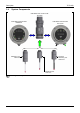
Operation 2.3 TP-R-400 Optical Status Display Subsequent table gives an overview of the blinking patterns of the LED ring (Fig. 16) and their meaning. LED ring blinking green LED ring blinking green/red LED ring blinking orange LED ring permanently red LED ring permanently blue (for 5 s after battery is inserted) LED ring permanently green (for 5 s after battery is inserted) Touch probe is transmitting signals LOW BATTERY Stylus deflected Error Touch probe starts (MY21.00/ PP41.