
Data Sheet
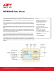
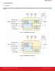
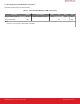
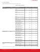
Table Of Contents
- Table of Contents
- 1. Features List
- 2. Ordering Information
- 3. System Overview
- 4. Electrical Specifications
- 5. Typical Applications and Connections
- 6. Pin Descriptions
- 7. Package Outline
- 8. Land Pattern
- 9. Top Marking
- 10. Tape and Reel Specifications
- 11. Software Reference
- 12. Certifications
- 13. Revision History

4. Electrical Specifications
All electrical parameters in all tables are specified under the following conditions, unless stated otherwise:
• Typical values are based on T
A
= 25 °C; V
VDD_IO
, V
VDD
, V
VDD_PA
= 3.3V
• Radio performance numbers are measured in conducted mode, based on Silicon Labs reference designs
• WFM200S features and benefits depend on system configuration and may require specific driver, firmware or service activation.
Learn more at https://www.silabs.com/products/wireless/wi-fi
Refer to Section 4.2 Operating Conditions for more details about operational supply and temperature limits.
4.1 Absolute Maximum Ratings
Stresses above those listed below may cause permanent damage to the device. This is a stress rating only and functional operation of
the devices at those or any other conditions above those indicated in the operation listings of this specification is not implied. Exposure
to maximum rating conditions for extended periods may affect device reliability. For more information on the available quality and relia-
bility data, see the Quality and Reliability Monitor Report at http://www.silabs.com/support/quality/pages/default.aspx.
Table 4.1. Absolute Maximum Ratings
Parameter Symbol Test Condition Min Typ Max Unit
Storage temperature T
STG
-40 — 150 °C
Junction temperature TJ
MAX
-40 — 125 °C
RF power level at RF1 and
RF2 ports
P
RFMAX
— — 10 dBm
Supply voltage to VDD_PA,
VDD_IO, VDD
VDD
MAX
-0.3 — 3.6 V
Voltage on all other pins
(GPIO, Host interface, PTA,
etc.)
VG
MAX
-0.3 — VDD
IO
+
0.3 V
V
Current into any GPIO pin IO
MAX
— — 20 mA
Sum of current into all GPIO
pins
IO
ALL_MAX
— — 150 mA
Range of load impedance at
RF1 and RF2 pins during TX
LOAD
TX
— — 10:1 VSWR
WFM200S Data Sheet
Electrical Specifications
silabs.com | Building a more connected world. Preliminary Rev. 0.51 | 8