
User's Guide

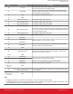


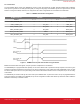
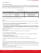
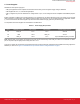

Table Of Contents
- 1. WFM200 Pinout
- 2. Device Configuration
- 3. Features Description
- 4. Power Supplies
- 5. Application Schematic Recommendations
- 6. Typical Application Schematics
- 7. Layout Recommendations
- 7.1 Generic RF Layout Considerations
- 7.2 GND and RF Pads Including the Diversity Port and External Antennas
- 7.3 Module Antenna
- 7.3.1 Small Board Size Recommendations for Good RF Performance
- 7.3.2 Extended X Dimension Recommendation for Good RF Performance
- 7.3.3 Y Dimension (65 to 80 mm) Recommendation for Good RF Performance
- 7.3.4 Y Dimension (80 mm or Larger) Recommendation for Good RF Performance
- 7.3.5 WFM200 Portion One Corner Bias with 3 mm Metal Keep-Outs
- 7.3.6 Recommended Antenna Loop Trace Capacitor Values
- 7.4 WFM200 Reference Evaluation Board
- 8. Recommendations for Certification
- 9. Package Outline
- 10. Integral Antenna Loop and Keep-Out Required Dimensions
- 11. Recommended PCB Land Pattern

3.2 Host Interface
The host interface allows control of the WFM200 by an MCU or SoC using either SPI or SDIO. Selection between SPI and SDIO is
done upon the logic state on the SDIO_DAT2/HIF_SEL pin during the rising edge of the RESETn signal. If this signal is HIGH, the host
interface is configured as SDIO; otherwise, it is configured as SPI. These configurations are summarized in the table below:
Table 3.1. WFM200 Host Interface Configuration
WFM200 Pin Name SPI Mode SDIO Mode
RESETn 0 → 1 1 0 → 1 1
SDIO_DAT2/HIF_SEL 0 x 1 SDIO_DAT2
SDIO_CLK/SPI_CLK x SPI_CLK x SDIO_CLK
SDIO_CMD/SPI_MOSI x SPI_MOSI x SDIO_CMD
SDIO_DAT0/SPI_MISO x SPI_MISO x SDIO_DAT0
SDIO_DAT1/SPI_WIRQ x WIRQ x SDIO_DAT1
SDIO_DAT3/SPI_CSn x SPI_CSn x SDIO_DAT3
Figure 3.1. WFM200 Power Up and Host Interface Timing Parameters
Besides the host interface main signals, a couple of pins also complement the host interface.
The GPIO/WIRQ pin is programmable and optionally can be used in SDIO mode to provide the interrupt request to the host if a given
host does not support in-band IRQ. In SPI mode, the pin can be configured as a copy of SDIO_DAT1/SPI_WIRQ IRQ. The pin can also
be used to wake up the host if it is in a power saving mode with the host interface inactive. If this is not required, the pin can be config-
ured as GPIO.
The GPIO/WUP pin should be used by the host to wake up the WFM200 when in power-save mode. This pin is programmable and if
power save mode is not enabled on the WFM200, this pin can be configured as a GPIO. Note that this pin should be LOW to enable the
WFM200 to reach sleep or shutdown modes.
UG395: WFM200 Hardware Design User's Guide
Features Description
silabs.com | Building a more connected world. Preliminary Rev. 0.1 | 7