...•..~ .. :,.,..' ... ~ ~ .I REFERENCE MANUAL SHUGART 706/712 HARD DISK Silicon Valley Computer .'.
- ~ - ~ - " TABLE OF CONTENTS - ~ - .~ - ~ - ,~ Page TABLE OF CO~S . . . . . . . . . . . . . . . . . . . . . . . . . . . . . . . . . . . . . UST OF AGURES UST OF TABLES ABBREVlAllONS/MNEMONlCS - ~ : .~ - -, , ' 1.4.5 R~d/Write'Headsand Disk(s) . . . . . . . . . . . . . . . . . . . . . . .. . . . . . . . . . . . . . . . . . . . . System n Altratio 1.4.6 A1r . . . . . . . . . . . . . . . . . . . . . . .. . . . . 1.4.7 Spindle Lock and Brake. . . . . . . . . . . . . . .. ...
TABLE OF CONTENTS (CONT.) ) . Wrtte Fault . · · · · · · . · · · . · · .. ············· 2.3.5 Seek Comple te · · .. · . · · · .. · . · · · · . · .. · 2.4 Data Transfer Unes . Data Write 2.4.1 ~ . 2.4.2 ~ Read Data ······.···· · · 2.5 Select Status •••.. •..... ...... . 2.6 Genera l Timing ReqUirements ...... ...... .....• .....• ··.·.·····.· 2.7 Power Interface ········.·.· · · · · · 2.8 Frame Ground ing 2-7 2-7 2-7 2-8 . . · · . · · · · · .. · ·.·· · · . · · . · .. · · · .. · · · · · · ..
TABLE OF CONTENTS (CONT.) , 8.3.3 Microprocessor Control Fault indicator Function · . . . . . . . . . . . . . . . .. 8.3.4 . Seek Function lnitiallzZltion ·.···.· ~ . . . . . . . . . . .. 8.3.5 Inttialize Code End · . . . . . . . . . . . . . . . . . . .. 8.3.6 Spindle Motor Background. . . . . . . . . . . . . . . . . . . . . . . . . . . . . . . . . . . . . .. 8.3.7 Motor Status Monitor. . . . . . . . . . . . . . . . . . . . . . . . . . . . . . . . . . . . . . . . . .. 8.3.
LIST OF FIGURES ) Figure I-I 1-2 1-3 1-4 1-5 2-1 2-2 2-3 2-4 2-5 2-6 2- 7 2-8 2-9 2-10 2-11 3-1 3-2 3-3 3-4 4-1 6-1 7-1 7-2 7-3 8-1 8-2 8-3 9-1 9-2 10-1 12-1 12-2 13-1 13-2 14-1 Title Page Shugart 706/712 Rigid Disk Storage Drive Read/Write Head Positioning Mechanism AIr Filtration System · Spindle Lock Shipping Zone J51nterface and Jl Power Connections. . . . . . . . . . . . . . . . . . . . . . . . . . . . . . . . . . . . . . . . . ..
-.-• .. I - • , "-, - .... I - • LIST OF TABLES t -. • - -• Table . 2-1 - -- " 2-2 6-1 8-1 8-2 ~ - -a - - 9-1 9-2 -- -• -- - 12-1 .. 12-2 12-3 13-1 A-I ~ Page Tltl. . . . . . . .. 2-5 False. 0 = True) · · · · · · · · . · . . . . . . . . . . . . . . . . . . . . . . . . . . . . Head Select (1 · · . . . . . . . . . . . . . . . . . .. 2-9 DC Requir ements · · · .. · · · . · . · · · · . · · · . · · - · · . . . . . . . . . . . . . . . . . .. 6-2 Write Precom pensati on · · · · · · · .
ABBREVIATIONS /MNEMONICS BKPC Background Port C MFM Modified FM bpi Bits per Inch MLC Machine Language Code eRe Cyclic Redundancy Check PCB Printed Circuit Bo.
- '" - 3 } : , .~ SECTION I INTRODUCTION =I~ : ·3 I~ : :: ;~ -~ 3 .. ~ 1.1 This publication is designed as a reference source for OEM engineers. system Integrators. service and maintenance technicians. and knowledgeable end users. It is assumed that the reading audience is sufficiently versed in the stateof-the-art with respect to rigid disk drives . 1.2 :3 .. ., . -- t The 706/712 interface is either ST506 or ST412 compatible, allowing easy integration into existing systems.
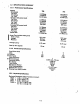
1.3 SPECIFICATIONS SUMMARY 1.3.1 Performance Speclflcatlona Capacity Unformatted Per Drive Per Surface Per Track Formatted (33 sectors/track) Per Drive Per Surface Per Track Per Sector Formatted (32 sectors/track) Per Drive Per Surface Per Track Per Sector Transfer Rate Access Time (includes settling time) Track to Track Average Maximum I Average Latency 706 712 6.4 Mbytes 3.2 Mbytes 10,416 bytes 12.7 Mbytes 3.2 Mbytes 10,416 bytes 5.2 Mbytes 10.3 Mbytes 2.6 Mbytes 2.6 Mbytes 8.
1.3 SPEC lFlCAn ONS SUMMARY 1.3.1 Pafor maace SpecUicadoD8 Capacity Unformatted Per Drive Per Surface Per Track Formatted (33 sedon/ track) 706 712 6.4 Mbytes 3.2 Mbyte. 10,416 byte_ 12.7 Mbytes 3.2 Mbytes 10,416 bytes 5.2 Mbytes 2.6 Mbytu 8.4 kbytes 256 bytes 10.3 Mbytes 2.6 Mbytes 8.4 kbytes 256 bytes 5.0 Mbyte. 2.5 Mbyta 10.0 Mbytes 2.5 Mbytes Per Drive : Per Surface Per Track Per Sector Formatted (32 seeton/track) Per Drive Per Surface Per Track Per Sector 8.2 kbyta I 8.
.~ ~ ,...- .... .j , ~ ....'.9 .. .oj ... Ij . , Host Ambient Temperature: Operating - 41 ° to 113°F (5° to 45°C) Non-operating - _40° to 140°F (_40° to 60°C) Temperature Gradient:· . Operating - 10°F (5.~OC) per 1/2 hour Non-operating - 212°F (100°C) per hour non-condenllng ~ ..- .~!t --- ., -- Relative Humidity: Operating - 8% to 80% Non-operating - 1% to 959.» Maximum Wet Bulb: Operating - 78°F (25.
1.-4.2 Read/Write anel Control Electroalea The standard ~iaoproceS50r and electronics are packaged o~ one printed circuit board containing the foUowing circuits: a. Index Generator Circuit b. Head Position Actuation Drivers c. Read/Write Amplifiers d. Drive (READY) up to Speed Circuit e. Drive Select Circuit f. Write Fault Detection Circuit g. Read/Write Head Select Circuit h. Ramped (Buffered ) Stepper Circuit I. Track 00 Indicator j. Brushless Spindle Motor Control Circuits 1.4.
ACTUATOR SPINDLE ASSEMBLY BAND PJW HEAD ASSEMBLY * STEPPER .MOTOR FIGURE 1·2. READ/WRITE HEAD POSITIONING MECHANISM 0.3 MICRON BAROMETRIC FILTER . COVER * CAPSTAN 0.3 MICRON FILTER FIGURE 1·3.
1.4.7 , Spindle Lock and Brake These drives are provided with an integral fall·sal. spindle lock and brake. ThIs lOIenold operated. mechanical brake is actuated when de power is applied to the drive, allowing the spindle to rotate. When the drive is powered off, the solenoid is deae:ttvated allowing the brake to engage the spindle. This prevents the possibility of disk move· ment during shipping or movement of the drive.
130 mm DISK 00 - DATA TRt< 00 TRACKS .'@ .... :~ -- ..... : .. ~ - .:1 • lJ ., " u . " I, .. · l .• l HEAD SHIPPING ZONE 40mm CYLINDER 353 DISK 10 FIGURE 1·5. SHIPPING ZONE ._' 1.5.3 Track Acceaalng .. , Read/write head positioning is accomplished by: a. Deactivating the WRITE GATE. .. , b. Activating the appropriate DRIVE SELECT line. , c. Being in the READY condition with SEEK COMPlETE true.\ d. Selecttng the appropriate direction. e. Pulsing the STEP Un•. f.
1.~4 Reacl OperaUoUl Reading data &om the d1sk Is accompUshecl by: a. Deactivating"the WRITE GATE line. r b. Activating the appropriate D~ SELECT line. c. Assuring that the drive d. Selecting the appropriate head. ts READY. 1.5.5 Write Operation Writing data onto the disk is accomplished by: a. Activating the appropriate DRIVE SELECT Une. b. Assuring that the drive is READY. c. Clearing any write fault conditions (if that exist). by reselceting the drive. d. Selecting the proper head.
- J · .J • • .J • .1 : -' : :~ , SECTION II ELECTRICAL INTERFACE 2.1 INTRODUCTION The interface for a 706/712 has drive control signal pin ualgnmentl per Industry standards. See figure 2·1 for the pin assignments. 7OeI712 , HOST • RESERVED l. - RESERVED .1 .. -WRITE GATE -SEEK COMPLETl 2 3 -• -• 5 7 • ~ 1 -TRACK 00 t 10 " (. I' 13 -- t. 15 - 11. 17 '1 11 -WR'TE FAULT .1 - -HEAD SELECT 2' RESERVED '. FLAT tC AlIBON -HEAD SELECT 20 FT. MAX.
The sJgna11nterface consists of three categories: I a. Control Input Una b. Control Output Una c. Data Transfer Una AD control lines are digitalin nature and either provide signals to the drive (input) or provide signals to the host (output) via the interface connector JS/P5. The data transfer slgnall are differentialln nature. They provide data either to or from the drive. via J6/P6. See figure 2-2 for the J6/P6 pin assignments.
-- i .... ~ l·~ - 20 FT (MAX) (6.0 mm) ... ") ~l .. ! t -. .. ... ~ : ~ --- .. ill .~ True False -- • -- .• -- •. -=- 0.0 to 0.• V de fl lin = .0 mA (max) lin 0 mA (open) = 2.5 to 5.25 V de " -- = 3i026-06·A FIGURE 2·3. CONTROL INPUT DRIVER/RECEIVER COMBINATION ~ - .~ -- ... - . • C!I REAR VIEW .1 -- ..tI • II - II DRIVE SELECT. · . - ·• a. • • 'II .... 3./. UNDEFINED WRITE GATE HEAD SELECT 21 DRIVE ALWAYS NOTE: These eight Jumper.
2.2.1 .. DrIve Select 1-4 DRIVE SELECT, when logically true, connects the drive to the control Una. Only one DRIVE SELECT line may be active at a time. ) Jumper options 051-4 are used to choose which DRIVE SELECT lin. wID activate the Interface for that unique drive. See figure 2-4 for the jumper locations. . 2.2.2 Direction 10 This signal defines the direction of motion of the read/write heads when the STEP bne Is pulsed. An open ctrcult, . or logical false.
-- : . -. -STEP : _I ... : -SEEK COMPLETE -DRIVE SELECT X NOTE: : '.' VARIES WITH SeEK L~NGTH. 11•• mMC MIN, .a.o maec MAX. FIGURE 2·8. BUFFERED STEP MODF Shipping Zone : ..' • The read/write heads can be accessed to the shipping zone by doing. seek to cylinder 353. NOTE STEP pulses with periods between 200 "sec and 3.0 msec are not permitted. Seek accuracy is not guaranteed If. this timing requirement is violated. u .1 2.2.
f ') 2.2.5 Write Gate I The active state of this signal (logical 0 level) enables WRITE DATA to be Written onto the disk. The inactive state of the signal (logical 1 level) enables data to be transferred from the drive and STEP pulses to reposition the head arm. See figure 2-7 for the tlm1ng sequences. I ~I 2.2.6 Reducecl Write ClII1'eDt and Precom,...AtloD f The 706/712 provides for automatiC reduced write current switching.
-- :i .... ] ., - :, 2.3.4 Write Fault '- t - .l .. ~ This signal. when active (logical 0), Is luued to indicAte. condltlon exists at the drive that could cause improper writing on the disk. A WRITE FAULT occun whenever one of three conditions occurs: - -- :~ -- ., -- The read/write heads are Improperly ..Ieded., b. The dc volta~e Is more than 2S percent out of tolerance. c. The actuator or spindle controllystem II faulted.
2.4.1 MfM Write Data This pair of signals defines the transitions (bits) to be written on the dlIk. + MFM WRITE DATA going more positive than -MFM WRITE DATA will cause • flux reversal on the track under the selected head providing WRITE GATE 15 active. This signal must be driven to an Inactive state (+ MFM WRITE DATA more negative than -MFM WRITE DATA) by the host system when in the rod mode. Figure 2·10 aho.WI the timing for MFM WRITE DATA. - DRIVE SELECT - HEAD SELECT --, ---, 81ls ec MAX .J f.
- 0' .~ ~ DC POWEAON j - ., DISK AT SPEED =.~ -READY : 'o! ~ - ~. - ~ . ~ ~ J _ r--- 9.0 SEC MAX J ~ _ 1__ male TYP I ~ ~ 46 male MAX 18 -SEEK COMPLETE -----~i * -- FIGURE 2·11. GENERAL CONTROL TIMING REQUIREMENT 2.7 POWER INTERFACE These drives require only dc power for operation . The de power to a 706/712 drive Is via connector Jl/Pl located on the solder side of the PCB.
• .. • :, . •• . .. SECTION III PHYSICAL INTERFACE ·-a -.a 3.1 INTRODUCTION . .. II - • The elecmcallnterface between a 706/712 drive and the host system Is via three connectors. The first connector, Jl. provides the de power: the second connector, J5. provides the control signals for the drive; and the third connector. J6. provides for the radial connection of the read/Write Ilgnals. II I u • .. " • I J6 --~~ P6 ---- P5 I ---------- JIl ____..........""'.
3.3 J5/P5 CONNECTION Connection to J5 is through a 34-pln PCB edge connector. Th. dimensions for this connector are shown In figure 3-3. The pins are numbered 1 through 34 with the odd numbered pin, located on the component side of the PCB, aJ. and even pins located on the solder side of the PCB. Pin 2 Is located at the end of the PCB connector closest to t h e : Jl connector and is labeled. A key slot is provided between pin. 3 and 5.
.. ,.. .- ) .. SECTION IV PHYSICAL SPECIFICATIONS . , 4.1 MECHANICAL DIMENSIONS See figure 4-1 for the dimensions of the Shugart 700 Mries drives. . .1 163 • 0011·0.02 + Z SIDE t 141 • • 0.31-0.5) -~ \------ 1.00 1203.2) MAX - - - - ... 038 : 002 It I : 0.5) -"- 1. ----------T I( t SWAY SPACE 007511 9) MIN· 3.12 : 0 a,s 171.3 : 0., 1-32 MOUNTING HOLIS ca • • • s.02 (21.1) o · .. " · .\ - 5 II • 0031· 001 114t • • 01 02) 5~ • 002 1131 7 : 0 ~J ~ 7~ • 0 01~ C1~0 • 04.
( o 4.2 MOUNTING c The 706/712 drives are capable of being mounted In any position. C CAunON' ,These drives must 1),e mounted wtth four machine screws. The screws may be installed In either the vertical or horizontal plains into the Iide rads. The saews must be torqued to ten inch/pounds. The required sway space is 0.075 inch. t C C C ( t t t t f f f f ~ ~ ~ ~. I 6: I ~ C C , $ .
• c ~ , -, . ( SECTION V MEDIA DEFECTS AND ERRORS • I - I • & • I 5.1 ERROR MAPPING AND QUALIFICATION In high density digital recording storage systems, it is necessary to Increase rellabdlty and Improve operational performance. This is done by providing an error detection and correction scheme. For disk storage systems, the predominant error pattern is a burst of etlon occuring in one or more tracks·. These errors are drop-outs (absent bits).
5.1.4 Error Map (J All drives are scanned for hard etTon during the manufACturing process. AU hard errors (media defects) are logged and an error map is attached to each drive. Each defed listed contains the foUowing information a. Track number b. Head number c. Byte count accurate to ± 4-bytes (Indicates the defective bytes as a location from physical index) d. Length of defect in bits I I .
• I - -. J ~ •• J .... ("-' '. .. ... SECTION VI RECORDING FORMAT -: .' 6.1 TRACK fORMAT The pupose of a format is to organize a data track Into smaller, Mquentlally numbered blocks of data called sectors. The 706/712'5 format is a soft sectored type. which means that the beginning of each sector is defined by a prewritten identification (10) field which contains the physical Hctor 'address, plus cylinder and head information. The 10 field is then followed by a user data field. ' ..
physical position "drift" of the index pulse as a functton of drive ~emperature. Gap 1 should be at least 22 ~1es (30 bytes recommended) 10llg to correspond with the head switching time and index drift. Gap 1 is immediately followed by a sync field for the 10 field of the first sector. 6.2.2 Gap 2 Following the 10 field. and separating it from the data field, is Gap 2. Gap 2 provides a known area for the data field write update to occur.
.. . • - • • ,J • ' . '-J 0" ( \ • oJ t ·- SECTION VII CUSTOMER INSTALLABLE OPTIONS • •J -. • J .J e - • · .l · .. • e 7.1 FUll-HEIGHT FACEPLATE KIT • • ..I One of the customer instaUllble options currently available for the Shugart 706/712 disk drives is the Full-height Faceplate Kit, PIN 061597-0. See figure 7-1. . • .J 0.-~ .J - J - • .J - ( @ -, I - e_ I •• J --.-• - · ,- • ·-,,.. • · , ., ·· .-- • \ -• e_ . ) ··.. ·.-•_1 0' ·• ',-1- .
7.2 LOW-POWER SLOW START JUMPER In certain system configurations It may be desirable to use a Low-Power Slow Start mode of initialization of the drive. In cases when this Is necessary. the mode can be selected by grounding pin 13 of the microprocessor. ( ) On early versions (i.e. t MLC 4 only) of the 706/712 PCB (PIN 26141 and 26159) this is accomplished by shorting between pins 12 and 13. See figure 7-2. . PIN 12 PIN 13 • (SHORT THESE PINS) FIGURE 7·2.
- .. .. ,,- I • - a.'. ) . .. -II SECTION VIII THEORY OF OPERATIONS - I-. - I 8.1 INTRODUCTION -. - -. I .. All of the tasks of the PCB miaoprocessor are separated into the following groups: -' • a. High priority time aitical tasks b. Lesser priority time critical tasks. c. System initialization tasks _I • • SPINDL£ BRAKE . · . I · I ) POWER ON · I · .. t RESET STEPPER MOTOR - - ·••... I · ··'-'- ~ ~ .. SPINDLE MOTOR ~ • 110 - ~ : CONTROLLER ......
8.2 HIGH PRIORITY CRITICAL TASKS (fOREGROUND) The high priority time critical tasks consist of the following: measure the revolution time. a. Generate the spindle motor waveform and b. Deted and accumulate the step pulses from the Interface. c. Generate the stepping waveforms applied to the stepper motor, and perform the actuator velocity ramping (up and down) including pulse width modulation. d. Time out the actuator damping interval.
-· •.. • ·· • I ~ -• 4) OFFE ' "" _I - .. • -- ,..• -- -• ·- -• -• ·- • • ) INTERRUPT REQUEST VECTOR OCD1 EVERY 10 liMe IENTRY I " FOREGROUND LOOP CONTROL occe SPINDLE MOTOR ' FOREGROUND ERAA 0003 _I MOTOR FAULT • FOREGROUND -~ I - • - -- L - « -· Ij STEP INPUT -- BUFFERING I.' FUNCTION a.' Oc.A • DAMA a' -· ..." · • U' : 1{1 STEPPER DAMPING TIME OUT ROUTINE . 0078 .. ·· '.~ ·• '.!.
8.2.6 Seek FunctioD Foregrouacl The seek flag is set from the Seek Ramping Calculate Function (background). Uthe seek flag is set, then a step delay is provided to allow time for step settling. Uthe delay is not done. then the routine exits to Foregr~und End and Interrupt Return. Otherwise the routine gets a ramp table value and determines if ramping is up or down. It ramping is down and seek is complete.
. ·• , ·· .. D • J •J ·· ·...-• j This is accomplished by allowing the beginning of background loop execution t~ proceed only on every fifth foreground interrupt. Therefore, background loop execution time is 450 p.SeC (5 x 90 I£Sec). The only exception to this Is that the spindle motor background control routines ar. exempted from this "gating" process In order to minimize control system phase error. The less time atticaJ tasks consist of the foUowing: -· ,.
SYlE... STAAT PORT PAE. 'YES yel IMTA 0878 SPINDLE MOTOR IN'T DRIVE ACTUATO R WARM UP SETTLING EXTN COUNT DN SELF·EXE RCISE FUNCTION IKGA OA3O YES SYSTEM YES IACKGND LOOP CONTROL LUBA FAULT 0822 ,.P CONTROL FAULT INDICATE FUNCTION ACTUATO R LUBE UNSTICK ROUTINE NO 0917 AREA SEEK FUNCTION INIT.
- I· -.e, 8.3.3 f • L - • 1:.' M~croproc...or Coatrol Fault ladlcator FUDCtI~ This routine removes power to the spindle motor and Rapper motor; th8 foreground interrupts are halted, and the . READY line is set false. The FAULT latch Is pulled and: a. If no jumpers are InstaUed, or If the delay Jumper (EI) 1I1nstaDed. then aU motor power II removed and the LED is flashed u shown In tabl. 8-2. b. If only the exeidse Jumper (E2) IIlnstaU8d.
8.3.9 Syatem Background Loop Control If five 90 Jolsec foreground loops have occurred since thal.5t time thiS funetton was entered, then control proceeds to Loss of Index Monitor; otherwise control goes back to Spindle Motor Background (paragraph 8.3.6). 8.3.10 Lo.. of Index Monitor If INDEX has not occurred during the last 115 msec. then control goes to the Control Fault Indicate Function (paragraph 8.3.3); otherwise control proceeds to Cylinder Address Rezero Monitor. . 8.3.
. ·· . 0 -· . ,'''';'-:''.' ,] o t • .u 8.3.16 Write Curren t Contr ol Functi on r address (TRKL and TRKH) is This routine sets + REDUCE IW lignal on port C. bit 6 high. when the cybnde See table 8-1. greater than the write cUlTent switchovcr point (WRITS~). The routine' then passes control to Drive Seled LED Monitor. 8.3.17 DrIve Select LED Monitor - U,J : (~ - I.J the drtve Is selected. U it Is. bit 3 in This function checks port 0. bit 7 (+ SEl).
SECTION IX PACKAGING INSTRUCTIONS 9.1 UNCRATING Due to the integral spindle actuator lock, no spec14llnstrudlonl for unaating or packaging are required. The Shugart 706/712 drives are shipped in two manners .. follows: a. A single unit In a single carton (figure 9·1). b. Ten units in a single carton (figure 9·2). It is suggested that packing materials be kept in case the unit must be returned to Shugart for repair. Regardless.
, t 3: f t t t t t t t t t t :~ f t f f , , , , f f ~ ~ E ~t FIGURE 9·1.
~.
t ( "9.2.3 FUDetiODU latinS Shugart recommends using the ACe T-650 Tester wtth Lev.1 E-6 Software. This tester Is speCiaDy programmed for aU 5.25 and 8-inch fixed disk products.' The functional tests performed by the ACe Tester arc as follows: o IP :I () is ( . f Prompt character and Indicates the program is rcady to accept Commands from the user. = Inspect Phase command code t ( availAble for displaying the contents of a phase. t PP = Print Parameters. See table 9-1 t TABLE 8-1.
• •"• ·- • , J - I .J ( ) -1.1 SECTION X DRIVE INTERCONNECT • ! , • : .J • • J The electrical connection between the Shugart 706/712 and the controi system Is shown in figure 10-1. For daisychain configurations, the terminating networks must be r.moved from aD but the last drive in the chain. Refer to - - • oJ · paragraph 2.3. · • .1 HOST 7061712 .J J6 DRIVE 1 - JI J1 CONTROlLER • J - • J J5 ·• J (... ) • J · ·] DRIVE 2· JI J1 ------ ·· .J - · .- J5 , ~ .. • ·· ..' ·.
SE CT IO N XI 'SPARE PARTS , available a dedicated and profesto provide service to Its customers, hasas well as the end user. t men mit com its in , tion pora Cor Shugart up to support the OEM cUllomer base sional Spare Part/Logistic support gro t 11. 1 ROUTINE OR DE R ENTRY ation by phone. facsimile. . may be placed with Shugart Corpor ing purchase documents U.S the In ) unts acco n ope estic (dom ire confirm Routine orders wUl be boo~ed as received but will requ TWX, or by mail.
SECTION XII MAINTENANCE 12.1 INTRODUCTION The Shugart 706/712 has been designed to require no maintenance under normal operating conditions. This sec· tion will discuss those steps to be taken in the event of a .drive malfunction. 12.2 MAINTENANCE EQUIPMENT The only equipment required ls an ADC T-650 Tester and an oscilloscope. Refer to paragraph 9.2.3. for ADC test procedure. 12.3 DIAGNOSTIC TECHNIQUES The 706/712'5 are eqUipped with a self-exerciser that supplements any diagnostic requirements. 12.
fABLE 12·2. INSPECTION OF THE DRIVE" , " .t . .. , .' ~. ' , . , '. # 0• °.'0 0 • • ,- PR08LEII IS IN . l\~<'-:. , THEPCa.. THE DRIVE DESCRIPTION COVER DAMAGE/BEND IN COVER ETC.
- . • •• : .~ INSERT SHIM HERE - :, : o . :,~.. ..... ~ :\ t;:;;i. ~ .. ~ ... ~--_ @ ~: .... '6' ............... ~ @) @) I • • • • · o o ~8 I o I • • · , · , : , ," . FIGURE 12·1. LOCATIONS DIAGRAM c. rotor. d. .. , .. Insert a flexible 0.020 Inch (0.5 mm) .him between the brake pad and the spindle motor. Pull the PCB. from the connector end, allowing the brake pad to press firmly against the shim and spindle e Tighten the two screws labeled "A" to 5 'n/lb (0.
~ g. Push the brake pad awa~J : ·mn the spindle ,·otor to see that the brake has sufficie nt stroke to dear the spincUe. The stroke should be about 0.020 lnch (O.~ mm). h. After the five mounting saews have been properly tightened. fiD the saew heads with glyptol. 12.7 REMO VAL AND REPLA CEME NT PROCEDURES ~ () I 12.7.1 Removal of Contro l PCB The foUowing steps define the process to be followed for the removal of the Control PCB (see figure 12·2): a. Remove and retain the five mounting screws. b.
-" : =-: .. .. • - - Lower the Control PCB carefuUy on to the ..and-offs with the cables not interferring with the spindle motor. Be sure the spindle motor cable Is nlot sandwiched between the miaoprocessor and the baseplate. e. Insert the five mounting screws through the board and Into the stand-offs but DO NOT TIGHTEN UNTIL BRAKE ADJUSTMENT IS MADE (refer to paragraph 12.6). 12.8 ALIGNMENT PROCEDURES The 706/712 drives require no special allgnment. 12.9 PREVENTIVE MAINTENANCE . - d.
- J .-) .J J .8 : -) SECTION XIII ILLUSTRATED PARTS CATALOG : --' -J 13.1 . DESCRIPTION precede the parts listing and, when The Illustrated Parts Catalog (lPC)ls arranged 10 thlt the figure will always iately preceding it. immed p~ge hand left the possible. will appear directly above the parts list or on the part within the figure . The first number in the list will aly/ays refer ~o the ref.
Tf..---2 I II I I I ....... ~ __ ' I .....-~,..",a ~::tIfIiI'/I~ I I I »tQ2-,. FIGURE 13-1.
._ .. ~ (. , ~ r" I REFERENCE NUMBER ( 1·1 PAJIT NUll." . .' DllCIUPTION ·28173-0 · CONTROL PCB (708) CONTROL PCB (712) 28177-0 2 3 ~ QUANTITY 1 12233-0 SCREW, PHILUPS. PAN HEAD ('~ x 5118) . WITH NYLON PAD 5 e121~2 fRONT PANEL AND RAIL ASSEMBLY 1 ( (. (oE .~ ~ (r (r €r . ~. ~~ €~ 3~02·19 €~ FIGURE 13·2. FRONT PANEL AND RAil ASSEMBLY €~ ( REFERENCE (~ (~ (~ (~ €C [b. PART NUMIER DESCRIPnON QUANTITY NUMBER 2-1 11306-0 SHOCK MOUNT . 2 81282·1 RAIL.
t ( · lS.4 RECOMMENDED SPARE PARTS STOCKING GUIDE The spare parts stocking guide is broken down Into three level'. The.. levels are: Site or F~eld Suppon Engineer (level 1). Branch Office (level 2). and Depot or Headquarter. (liv.1 3). The quantities listed assume that the Site is replenished by the Branch Immediately and the Branch replenllhad by the Depot within 30 Days.
,.. ~ .! .~ ...•- •I~ : i~ 's :1• IS II: . ~ ifi • ~I I~ I SECTION XIV SCHEMATIC DIAGRAMS. .. I ! :~ The following schematic diagrams are furnished to E J~ ! ! ~ i S .'d In malfundlon analysis. ~ --- i_. ~ ! ~ ! Ij e ~ ~ :~ ! ~~ • e ,;~ e ;~ r • ~.: I t) , ! ~ t) p ! t) I I i~t) t e:~ S!t s L. E!~ e l .. e·~ ~!~ t-fi) , • 14·1/1 4·2 (blank) ._-_.~.
~ 1 f .~ I . i ~ ,. o§ m~ -I 8 z ~I Jlt J.= ,fj !. ~ ~ ~ ~ "' :r: p; UI I -.. I;: CD ~ ~ ~ fa =- ,~;g ·~il i ~I ..'" 'c !i ! , . ,'I i· I ~ &9:1 -E alii! III § a!~ii I:; ; i-·!! !I: I ;!:I·;i -I- oo~S!. s~ lii,-! Ii I ='- a "I... v • •• 11 ..