SE2.8i - 3.8i - 4i - 5i Users manual Single-phase power grid-connected inverters Siliken Electronics S.L. Ronda Isaac Peral y Caballero,14 - Parque Tecnológico E-46980 Paterna - Valencia - Spain Date: 05/10/2010 Phone: (+34) 902 41 22 33 - Fax.: (+34) 96 070 92 65 electronics@siliken.com - www.silikenelectronics.
SILIKEN appreciates your support for our products. We recommend that you read this instruction manual carefully in its entirely before handling the Inverter.
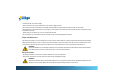
Safety SAVE THESE INSTRUCTIONS This manual contains important instructions of models SE5i, SE4i, SE3.8i & SE2.8i that shall be followed during installation, application and maintenance of the PV inverter. Safety Precautions/Safety Notes Only training-qualified personnel are allowed to perform the electrical installation, wiring, opening and repair of the SE inverters. Even if no external voltage is present, the SE inverters may still contain high voltage and the risk of electrical shock.
General Safety Precautions Training-qualified personnel are allowed to mount, reconfigure or repair this PV inverter. Also, licensed electricians are allowed to install and inspect the permanently-wired system. Remove all conductive jewelry or personal equipment prior to installation or service of the device, parts, connectors, and/or wirings. Ensure there is no grounding path through the human body. Well-insulated guards, e.g. insulated mat or shoes, are necessary when working the operating device.
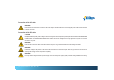
Install the inverter out of direct sunlight. Risk of electrical shock may be contained even if no external voltage is present. Allow at least 5 minutes for the inverter to discharge completely after disconnecting the AC and DC sources from the inverter. The temperature on the external heat sink may be high in normal operation and cause skin burn injury when touched. Pay attention to high temperature components. Prevent the risk of fire hazard, do not cover or obstruct the heat sink.
Connection of the AC cable WARNING! Reconfirm the circuit breaker connected to the main utility is switched OFF before connecting the power cable from the breaker to the AC connector. Connection of the DC cable ! CAUTION! Identify the different polarity of DC voltage on each PV string and connect respectively to the input terminals marked UNGROUNDED CONDUCTOR and GROUNDED CONDUCTOR. Make sure the DC voltage that PV arrays generate is equal to or less than 600 VDC in any case.
Table of Contents 1 Introduction ................................................................................................................. 8 1.1 General .............................................................................................................. 8 1.2 Specifications .................................................................................................... 9 1.3 Adjustable Parameter Settings .......................................................................... 10 1.
Table of Contents 3.1 Overview ...............................................................................................................30 3.2 Operation Feature .................................................................................................31 3.3 LED Indication ......................................................................................................31 3.4 LCD Display ........................................................................................................
Introduction 1.1 General The Siliken Electroncis SE product family is a series of grid-connected photovoltaic inverters which are designed to convert DC power generated by photovoltaic arrays to AC power that is delivered to the home loads and then fed into the utility grid with any excess power. The SE 2.8i, SE3.8i, SE 4i, and SE 5i are the members of the family for the European market. The overview of the grid-tied solar energy system is shown in figure 1.1.1.
Introduction 1.2 Specifications DC Input SE2.8i SE3.8i SE5i General characteristics Maximum DC power MPP Voltage range Maximum voltage range Maximum current Number of MPPTs Maximum number of Strings 3,3 kWp 4,5 kWp 4,8 kWp 200-550 VDC 600 VDC 20 A 22 A 1 4 4 6 kWp AC Output SE2.8i SE3.
Introduction 1.3 Adjustable Parameter Settings This new series of SE inverters have, currently, three models to fulfill the market needs for the countries of Germany, Italy, and Spain.
Introduction 1.4 Accessories Operation Manual Auto-Test software CD (SE xxE-IT only) 1 pc 1 pc 11 users manual inverter SE2.8i - SE3.
Installation 2.1 Placement 1. SE inverters that must be vertically mounted may be located indoors or outdoors, according to protection class IP44. 2. Leave at least 50 cm (19.67 inches) of free space above and 100 cm (39.37 inches) below the inverter when installed outdoors. Allow 20 cm (7.87 inches) between inverters when installing multiple inverters for better ventilation (see figure 2.1.1). 3. Mount the inverter on a wall that shall be strong enough to sustain the inverter with 32 kg (70.5 lb) weight.
Installation 2.2 Mounting The steps listed below describe how to mount the inverter on the wall: 1. After removing the inverter from the carton, the attached mounting bracket must be removed by sliding the bracket down and away from the inverter as shown in the figure 2.2.1 below. Fig. 2.2.1 Removal of the mounting bracket from the inverter users manual inverter SE2.8i - SE3.
Installation 2. Use the mounting bracket (figure 2.2.2) as a template to mark the location of the holes to be drilled in the wall. After drilling the holes, the mounting bracket is then held against the wall and fastened to the wall with anchors as shown in the figure 2.2.3. (A minimum of three (3) screws is required) (30)/(11. 81) (60)/(23.62) (7)/(2.76) (12)/(4.72) (30)/(11. 81) (19)/(7.48) (52.5)/(20.67) ) .73 /) (1 (12.5)/(4.92) .4 (4 (7)/(2.76) (25)/(9.84) (18)/(7.08) (40.5) /(15.
Installation 3. Once the mounting bracket is attached to the wall, the inverter can be located and fastened to the mounting bracket. Slide the inverter over the mounting bracket flanges and down carefully to lock it in place. Attach the screw through the hole as shown in figure 2.2.4 below, used to fasten both inverter and the wiring box together to the mounting bracket. Fig. 2.2.
Installation 2.3 Wiring the inverter The SE inverter is provided with four (4) (three (3) for SE 2.8i) independent PV strings to be connected in parallel in the wiring box. The wiring box of the SE inverter offers 3 options in DC cable connection, type DM, DS and S as shown in the figure 2.3.1. DM type wiring box has DC/AC disconnect switch and MC4 connectors built on the box. DS type wiring box has DC/AC disconnect switch built on, but there is no MC4 connectors for the DC wirings.
Installation Fig 2.3.2 Turn the DC/AC disconnect switch OFF Fig 2.3.3 Remove the cover of the wiring box 17 users manual inverter SE2.8i - SE3.
Installation In order to prevent from water, dust or any other unwanted foreign body, must stuff up all those unused cable glands (or MC4 connectors) with sealing pins (or MC4 sealing plugs), parts of accessories, when the wiring work is almost completed. See figure 2.3.4. Sealing Pin Sealing Plug Fig 2.3.4 Sealing pins (plugs) 18 users manual inverter SE2.8i - SE3.
Installation The following three sections describe the wiring for the AC, DC, and communication ports. The wiring shall be done in the wiring box for the SE 2.8i, SE 3.8i, SE 4i, and SE 5i. There is one (1) AC terminal block, a pair of DC terminal blocks and two (2) RJ-45 connectors in the wiring box as shown in the figure 2.3.5. The AC terminal block is used to connect to the utility grid through a circuit breaker and distribution panel according to national and local requirements.
Installation 2.3.1 Connection of the AC cable Use the following procedure to wire the AC cables. 1. Open the Distribution panel and switch off the circuit breaker used to connect the inverter to the grid. 2. Use #10 AWG to #6 AWG, 90°C (194°F) copper wire for all AC wiring connections to the SE inverter. 3. Connect the cable GND to the screw of the ground bar labeled Fig 2.3.1.1 AC Terminal Block for AC cable connections 20 4. Connect the cable L to the terminal labeled L of the AC terminal block. 5.
Installation WARNING! Reconfirm that the circuit breaker to the main utility is switched OFF before connect the power cable from the breaker to the AC terminal block. ! CAUTION! Ensure that the total impedance of the grid and the interconnected AC power cable shall be less than 1.25 .
Installation used for the DC cable connections. All the screws shall be tightened with a torque of 1.7Nm (15.6 in-lb). Up to four (4) (three (3) for SE 2.8i) independent PV strings (4 pairs) can be connected to the SE inverter as shown in the figure 2.3.2.1. The PV strings will be connected in parallel in the wiring box. Fig 2.3.2.1 PV-terminal connection The SE inverter supports both negative and positive ground for PV strings connections.
Installation ! CAUTION! When PV arrays are energized when exposed to light, it supplies a dc voltage to the inverter. Bear in mind the safe working practices are followed. WARNING! Route the DC connection cables to the SE inverters away from any possible hazards that could damage the cables. WARNING! Hazardous voltage is still present on the device after disconnection of all PV DC inputs. Allow 5 minutes for the inverter to discharge the energy stored in capacitors completely. 2.3.2.
Installation input voltage shall be connected to the terminal labelled GROUNDED CONDUCTOR. Avoid using wire nuts to join any wires together or to make any connections anywhere in the PV system. Wire nuts are a frequent cause of unreliable connections, resistive connections, and ground faults. Tighten the screws with a torque of 1.7Nm (15.6 in-lb). Fig 2.3.2.1.1 Negative Ground Setting and DC wires connections Fig 2.3.2.1.
Installation 2.3.2.2 Connection of the DC wires for Positive Ground Arrays The SE inverter also supports PV arrays with positive ground for some applications. As shown in the figure 2.3.2.2.1, the JP14 and JP15 jumpers are placed on the higher positions to set to the positive ground. And the red DC wire is connected to DCIN- terminal and the black DC wire is connected to DCIN+ terminal.
Installation CAUTION! The Positive Polarities of the DC input voltage from a PV string shall be correctly connected to the GROUNDED CONDUCTOR terminal and the Negative Polarity of the DC input voltage from a PV string shall be connected to the UNGROUNDED CONDUCTOR terminal. Make sure the DC voltage that PV arrays generate is equal to or less than 600 VDC in any case.
Installation The RS-232 signal pins, TXD and RXD, are only on the RJ45-L. Therefore, only the RJ45-L can be used to connect to one remote PC or terminal when the RS-232 interface is used. The cable with the part number of WABG-0918S, which is 180 cm (70.9 inches) in length, is dedicated for the communications between SE inverter and a computer. Its wire connection between RJ45 and RS-232 is shown in the figure 2.3.3.3.
Installation Fig 2.3.3.4 RS-485 connection 28 users manual inverter SE2.8i - SE3.
Installation 2.4 Wiring inverter in parallel SE inverters can be connected in parallel when more power is required. In the parallel configuration, each inverter shall connect to its own PV array. It is not recommended to connect one PV array to more than one inverter. This may cause the inverter to work abnormally. The figure 2.4.1 below shows the connections between inverters and PV arrays in parallel configuration. 3 7 Fig 2.4.1 Parallel configuration of inverter 29 users manual inverter SE2.
Operation 3.1 Overview The SE inverter will operate automatically. Once the insolation is strong enough to generate DC input voltage over the pre-set threshold value, the inverter turns itself on. The inverter feeds power into the grid after input voltage over the PV start voltage and all necessary conditions are checked and fulfilled. The inverter goes into Monitoring mode from the Grid/MPP mode if the DC input voltage is under the minimum MPP voltage.
Operation to the grid for safety reason. Normally this is a failure that cannot be removed on field. It needs service personnel coming to remove the problems and put the system back to operation. 3.2 Operation Feature Anti-Island: When an island condition is detected, the inverter will stop feeding the power to the grid and/or the load. The island is defined as a grid tied inverter maintaining operation and feeding power to a load that has been isolated from the utility power source.
Operation SE 2.8i Operation SILIKEN SE2.8i Inverter Failure Ground Fault Fig 3.3.1 Front panel of the SE inverter 32 users manual inverter SE2.8i - SE3.
Operation Led indicators Green Yellow Red Green Yellow Red Green Yellow Red Green Yellow Red Green Yellow Red Green Yellow Red Led Indication Table: Led On Operating status On Grid Description Initialization N The SE inverter is in initial mode. System Check mode N The inverter is in System Check mode. Monitoring mode N The inverter is in Monitoring mode. Grid / MPP mode Y The inverter is in Grid / MPP mode. Power De-rating Y Power de-rating is performed. Warning Y Warning is detected.
Operation Led indicators Green Yellow Red Green Yellow Red Green Yellow Red Green Yellow Red Green Yellow Red Led Indication Table: Led On Operating status On Grid Description 1. Low Insolation 2. Vac high N 1. The invertere is in low insolation. 2. Vac is higher than the voltage quality monitoring setting. Fault mode N The inverter is in Fault mode. Ground Fault N Ground fault detected. Idle mode N The inverter is in Idle mode. Night Time N There is no DC power coming from PV array.
Operation 3.4 LCD Display The SE inverter has a 2 x 16 LCD to show the operating status, input/output data, and error messages. As long as the DC input voltage is above the pre-set threshold value, the LCD will display the information following the process flow illustrated in the figure 3.4.1. The process flow could be the regular procedure, fault procedure or idle procedure.
Operation 3 seconds â After 3 seconds, software versions of two embedded CPUs, Sequential (SEQ) and Current (CUR) controller, will be displayed on the LCD. Afterward the serial number (S/N), the baudrate (BR) / address (ID) for the communication port will be displayed. S E Q V e r s i o n X . X X C U R V e r s i o n X .
Operation During the System Check, if the DC input voltage is not reaching the point of the PV start voltage setting, , then the following message will be shown on the LCD and the system will stay at this step. L o w I n s o l a t i o n During the System Check, if the grid is not connected to the inverter, then the inverter enters to Fault mode and following message will be shown on the LCD.
Operation 3 seconds â V p v X X X V 3 seconds â V A C X X X . X F A C X X . X V H z 3 seconds â During the Monitoring mode, if DC input voltages fall under the PV start voltage setting, the system stays in this mode and shows the information as follows. The system will still keep measuring the parameters of both DC and AC and display on the LCD. M o d e L o w M o n i t o r i n g I n s o l a t i o n 38 users manual inverter SE2.8i - SE3.
Operation 3 seconds â V p v X X X V 3 seconds â V A C X X X . X F A C X X . X V H z 3 seconds â For SE xxxxE (Germany type), according to VDE0126-1-1, if the AC voltage on the grid side increases and over the voltage quality monitoring setting and below the over voltage setting for at last 300 seconds in grid/MPP mode, the SE inverter shall return to Monitoring mode and display the messages on the LCD as shown below.
Operation 3 seconds â X X X V p v V 3 seconds â V A C X X X . X F A C X X . X V H z 3 seconds â Grid/MPP Mode : After the system enters the Grid/MPP mode, it will show the following information in order and repeatedly until the system goes to other operating mode. The first screen shows the current operation mode. M o d e G r i d / M P P 40 users manual inverter SE2.8i - SE3.
Operation 3 seconds â Next messages are the up-to-minute data of the input / output voltage and power. First two messages are for the PV arrays and the other two messages are for the output. Vpv is the incoming voltages from PV array. Wpv is the incoming power of PV array in watts. Vac, Pac, Iac, and Fac are the voltage, power, current, and frequency that the inverter feeds to the grid. V p v X X X V W p v X X X X W 3 seconds â V A C X X X . X V P A C X X X X W 3 seconds â F a c X X .
Operation 3 seconds â The next message shows the cumulated energy in kWh and period of time in hours for the inverter delivering the power to the grid since the inverter has been power on and operated for today. E t o d a y X X X . X H t o d a y X X . X k W h H r 3 seconds â The next message shows the cumulated energy in kWh and period of time in hours for the inverter delivering the power to the grid up-to-date since the inverter has been installed and operated. E a c H X X X X X X .
Operation message is presented, the power de-rating is caused by the over temperature. The Ipv message shows that the power de-rating is caused by restricting the DC input current to the maximum limit. The Iac and Pac messages illustrate the power de-rating is caused due to restriction of the maximum output AC current and power. The VacH message shows that the power de-rating is caused by the high AC voltage.
Operation Warning Message: There are three possible warning messages which be shown when situations occur in grid feeding mode. When EEPROM message displayed, the system has encountered a failure accessing to the EEPROM. For the COMM message, it represents failure of the communication function. For the FAN BLOCK message, it shows that the fan has stopped running. These warnings could be happening simultaneously.
Operation M o d e S / N F a u l t X X X X X X X X X X X X 3 seconds â S E Q V e r s i o n X . X X C U R V e r s i o n X . X X 3 seconds â M o d e E r r o r F a u l t M e s s a g e 3 seconds â There are several error messages that show the detailed conditions causing the system going into the Fault mode. Such as the messages shown below describe that the frequency on AC grid is too high (H) or too low (L).
Operation M o d e F a u l t F a c X X: H or L 3 seconds â a t X X . X H z P r e s e n t X X . X H z T r i p 3 seconds â The message below shows the AC voltage is too high (H) or too low (L). And after three (3) seconds, the message shows the present voltage and the voltage that caused the system to go into fault mode. M o d e F a u l t V a c X X: H or L 46 3 seconds â users manual inverter SE2.8i - SE3.
Operation T r i p a t X X X . X V P r e s e n t X X X . X V 3 seconds â The message below shows the PV input voltage is too high. M o d e F a u l t V p v H 3 seconds â T r i p a t X X X . X V P r e s e n t X X X . X V 3 seconds â Idle Mode: The messages for Idle mode are as follows. It shows the operating mode, serial number of the inverter, software versions of the sequential 47 users manual inverter SE2.8i - SE3.
Operation (SEQ) and current (CUR) controllers and then the error messages which are listed in the Error Message Table on section 3.7. M o d e S / N I d l e X X X X X X X X X X X X 3 seconds â S E Q V e r s i o n X . X X C U R V e r s i o n X . X X 3 seconds â M o d e E r r o r I d l e M e s s a g e 3 seconds â 48 users manual inverter SE2.8i - SE3.
Operation Initial Mode Siliken Electronics SE 5i 3 seconds SEQ Version X.XX CUR Version X.XX 3 seconds S/N 23WWYYXXX BR XXXXX ID XXX 1 second System Check Mode Low Insolation Fault Mode Mode System Checking Mode Fault S/N 23WWYYXXX 3 seconds Monitoring Mode SEQ Version X.XX CUR Version X.XX 3 seconds Mode Monitoring Low Insolation Mode Monitoring NewtConnect XXX s Mode Fault Error Message 3 seconds 3 seconds Vpv XXX V Vac Fac XXX.X V XX.
Operation 3.5 Auto Test This Auto Test function is stipulated in accordance with the Italian Standard DK5940. It enables verification of the voltage and frequency monitoring function. The Auto Testing software as an accessory provided with the inverter should be installed on a PC connected up the inverter through the RS-485 (or RS-232) port. Once the software is installed successfully, there is an execution file SE Inverter Auto Test created in the Start\Programs menu.
Operation It shows the serial number and the status of the inverter when communicated successfully. Whichever the preceding mode it is, clicking the START button is going to turn the inverter into the Monitoring mode automatically. Choose one inverter to run the Auto Test by highlight its serial number if more than one inverter is found. And then click the START button to start the Auto Test, which performs in order, users manual inverter SE2.8i - SE3.
Operation a. Maximum AC voltage threshold b. Minimum AC voltage threshold c. Maximum AC frequency threshold d. Minimum AC frequency threshold The standard threshold values and the trip time related to the specified sub test will be displayed on the PC screen before the Auto Test. a. Maximum AC voltage threshold: 262 V ; < 0.1 s b. Minimum AC voltage threshold: 188 V ; < 0.2 s c. Maximum AC frequency threshold: 50.3 Hz ; < 0.06 s d. Minimum AC frequency threshold: 49.7 Hz ; < 0.
Operation 53 users manual inverter SE2.8i - SE3.
Operation Once a sub test fails, the inverter will turn Monitoring mode into Fault mode and stop the test until the START button is clicked to restart again. If a sub test passes, the inverter will continue the remaining sub tests automatically after 5 seconds. When the inverter is under Auto Test, the following message will be shown on the LCD. A u t o T e s t i n g NOTE: If the Auto Test fails, the inverter will go into Fault mode and the error message will display on the LCD shown below.
Operation 3.6 Communication There are two types of communication methods, RS-232 and RS-485 supported in the SE inverters that may be connected to an external computer or terminal equipped with either RS-232 and/or RS-485. Only one type of the communication can be used at a time. SE inverter will automatically switch to RS-232 or RS-485 depends on the external communication interfaces without manual setting.
Operation Error Message 56 InvTempMax Relay 1 Open Relay 1 Close Relay 2 Open Relay 2 Close MOV Fault,AC MOV Fault,DC GFDI DCInjectCurH VdcbusH Internal COMM Watchdog Idc Test Offset Temp. Sensor RAM Test EEPROM Test System Error Version Error CPU Delta Fac CPU Delta Vac CPU Delta GFDI CPU Delta Idc IpvH Driver Fault CalDataError CalDataLoss Ibuck Over Converter Error Autotest Description The internal temperature of the inverter exceeded the safe operating limit. Relay 1 test open failed.
Warranty Information 4. Warranty Information Warranty Period A period of 5 years is warranted from the date of your purchase of the SE series Products. Warranty Terms SILIKEN ELECTRONICS, S.L.
Warranty Information 4. Transported, installed or operated contrary to this instructions of SILIKEN. 5. Opened, altered, modified or disassembled in any way without SILIKENs consent. 6. Used in combination with items, articles or materials not authorized by SILIKEN. SILIKEN reserves the rights to determine whether the problem exists within the Product.
Warranty Information some documents which be attached with the return Product. Please provide as much detail as possible. 1. Model number and serial number shown on the label. 2. Fault message on the panel and how it reproduces. 3. Detailed descriptions before & after the fault condition and the utility grid system connected. How Our Factory Service Goes On 1. Replace the defective Product with a new unit if it is purchased within 90 days. 2.
Warranty Information WARRANTY REGISTRATION FORM It is very important to you that you register the product. Changes in product technologies as well as new developments in software and features may make it necessary for us to notice you the related information about your inverter. Please register immediately after purchasing.
Technical Documentation 5.1 Outline Drawing SE 2.8i-DM SE 2.8i-DS Fig 5.1.1 Outline Drawing of SE2.8i-DM SE 2.8i-S Fig 5.1.2 Outline Drawing of SE2.8i-DS SE 3.8i-DM Fig 5.1.3 Outline Drawing of SE2.8i-S users manual inverter SE2.8i - SE3.8i - SE4i - SE5i Fig 5.1.4 Outline Drawing of SE3.
Technical Documentation SE 3.8i-DS SE 3.8i-S Fig 5.1.5 Outline Drawing of SE3.8i-DS SE 4i-DM, SE5i-DM 62 Fig 5.1.6 Outline Drawing of SE3.8i-S SE 4i-DS, SE5i-DS Fig 5.1.7 Outline Drawing of SE4i-DM, SE5i-DM Fig 5.1.8 Outline Drawing of SE4i-DS, SE51-DS users manual inverter SE2.8i - SE3.
Technical Documentation SE4i-S, SE5i-S Fig 5.1.9 Outline Drawing of SE4i-S, SE5i-S 63 users manual inverter SE2.8i - SE3.
Technical Documentation 5.2 Efficiency Efficiency of the SE2.8i Efficiency of the SE3.8i 99 99 97 97 95 95 93 % of Efficiency % of Efficiency 93 91 89 91 89 87 220 Vdc 220 Vdc 87 350 Vdc 85 85 83 0 10 20 30 40 50 60 70 80 90 350 Vdc 450 Vdc 450 Vdc 0 100 10 20 30 50 60 70 80 Fig 5.2.1 European Efficiency of the SE2.8i=95.4% 100 Fig 5.2.2 European Efficiency of the SE3.8i=95.
Technical Documentation 5.3 De-rating Operation The occasions when the SE inverter will take into account and then regulate the output and/or restrict the input power to ensure the system is in a safe operation are described in detail below. Temperature The SE inverter will monitor the temperature on the heatsink. Once the temperature exceeds 78°C (172.4°F) the system will reduce the output power until the temperature drops under the critical value.
Technical Documentation Output AC current The maximum current that the SE inverter feeds to the grid is limited according to the specifications listed in Section 1.2. Even if the output power does not up to the maximum power limit, the output current may still be limited in order to keep the output current within the maximum current limit. It often occurs in case the output voltage is lower then nominal AC voltage.
Technical Documentation 4000 500VDC 3500 375VDC 3000 250VDC Power (W) 2500 2000 1500 1000 500 0 45 50 55 60 65 70 Ambient Temp(C) 75 80 85 Fig 5.3.2 Temperature derating curve of the SE3.8i 4500 500VDC 4000 375VDC 3500 250VDC Power (W) 3000 2500 2000 1500 1000 500 0 45 50 55 60 65 70 Ambient Temp(C) 75 Fig 5.3.3 Temperature derating curve of the SE4i users manual inverter SE2.8i - SE3.
Technical Documentation 5500 5000 500VDC 4500 375VDC 4000 250VDC Power (W) 3500 3000 2500 2000 1500 1000 500 0 45 50 55 60 65 70 Ambient Temp(C) 75 80 85 Fig 5.3.4 Temperature derating curve of the SE5i 68 users manual inverter SE2.8i - SE3.
Technical Documentation 5.4 Maintenance 5.4.1 Exchange of the GFDI Fuse. As shown in the figure 5.4.1.1, turn the cap of the GFDI fuse holder counter anti-clockwise to open the cap and replace the GFDI fuse. Before replacing the fuse, turn off the DC/AC disconnect switch and the breakers and wait for at least 5 minutes for system to discharge. 1. Turn OFF the DC/AC disconnect switch and breakers. 2. Wait for at least 5 minutes. 3. Exchange the fuses. 4. Turn ON the DC/AC disconnect switch and breakers.
Technical Documentation 5.4.2 Factory Service Once the product is diagnosed requiring a Factory Service, the product could be removed and sent back using the original shipping box and the packing materials. A copy of the purchase invoice is also required to be included in the package. Document There are some documents must be attached with the return product. Please write as detail as possible. 1. Serial number and machine type of the inverter 2. Brief descriptions of connected system 3.
Technical Documentation Fig 5.4.2.1.1 Remove the cover of the Inverter Fig 5.4.2.1.2 Remove the DC and AC wires users manual inverter SE2.8i - SE3.
Technical Documentation Fig 5.4.2.1.3 Keep the well-wrapped DC and AC wires in store in the wiring box 72 Fig 5.4.2.1.4 Remove the screws and nuts bonding between the inverter and wiring box users manual inverter SE2.8i - SE3.
Technical Documentation Fig 5.4.2.1.5 Un-hang the inverter carefully Fig 5.4.2.1.6 Locate the cover plate in place and fasten the screws users manual inverter SE2.8i - SE3.
Technical Documentation 1. Turn the DC/AC disconnect switch to OFF position and turn off all breakers. 2. Wait for at least 5 minutes. 3. Remove the cover of the wiring box by following the steps described in section 2.3. 4. Remove the cover of the inverter as shown in the figure 5.4.2.1.1 5. Disconnect the red and black DC wires from the DCIN+ and DCIN- terminals, disconnect the brown and blue AC wires from the ACIN_L1, and ACIN_L2 terminal and disconnect the communication cable as shown in the figure 5.4.
Technical Documentation Fig 5.4.2.2.1 Re-install the cover plate and fix it on the top of the wiring box 75 users manual inverter SE2.8i - SE3.
Technical Documentation Fig 5.4.2.2.2 Hang the inverter into the mounting bracket carefully 76 Fig 5.4.2.2.3 Fasten the screws and nuts bonding between the inverter and the wiring box for construction and grounding continuity users manual inverter SE2.8i - SE3.
Technical Documentation Fig 5.4.2.2.4 Connect the AC wirings to their correct terminals individually Fig 5.4.2.2.5 Fasten the screws of cover of the inverter first and the wiring box then users manual inverter SE2.8i - SE3.
Technical Documentation 1. Turn off all DC/AC disconnect switch and breakers. 2. Remove the front cover of the wiring box by following the steps described in section 2.3. 3. Remove the cover plate used to cover the through holes of the wires and put it back to its original place as shown in the figure 5.4.2.2.1. 4. Remove the cover of the inverter and then hung it on the mounting bracket as shown in the figure 5.4.2.2.2. 5. Tighten the screws and nuts with a torque of 1.7Nm (15.
Technical Documentation the energy stored in capacitors completely. WARNING! Must confirm that all DC and AC circuit breakers are turned off for at least five (5) minutes before opening the front covers of the inverter and the wiring box and disconnect the DC and AC wires between them. The wires been disconnected must be wrapped with an insulated material to prevent staff from the electrical shock.
Notes 80 users manual inverter SE2.8i - SE3.
SE2.8i - 3.