
User`s manual

Installation
14
users manual inverter SE2.8i - SE3.8i - SE4i - SE5i
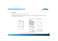
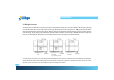
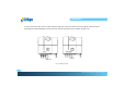
2. Use the mounting bracket (figure 2.2.2) as a template to mark the location of the holes to be drilled in the wall. After drilling the holes, the
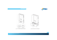
mounting bracket is then held against the wall and fastened to the wall with anchors as shown in the figure 2.2.3. (A minimum of three (3)
screws is required)
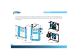
Fig. 2.2.2 Inverter mounting bracket Fig. 2.2.3 Fasten the mounting bracket
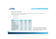
(7)/(2.76)
(12)/(4.72)
(19)/(7.48)
unit:cm/inch
(40.5)/(15.94)
(52.5)/(20.67)
(4.4)/(1.73)
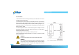
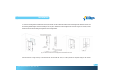
(7)/(2.76)
(12.5)/(4.92)
(18)/(7.08)
(25)/(9.84)
(60)/(23.62)
unit:cm/inch
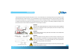
(30)/(11.81)
(100)/(39.37)
~(170)/(66.93)
(30)/(11.81)
The height of the anchor head <8mm(0.314 in)