
User`s manual


Installation
26
users manual inverter SE2.8i - SE3.8i - SE4i - SE5i
CAUTION!
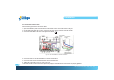
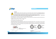
The Positive Polarities of the DC input voltage from a PV string shall be correctly connected to the GROUNDED CONDUCTOR
terminal and the Negative Polarity of the DC input voltage from a PV string shall be connected to the UNGROUNDED CONDUCTOR
terminal. Make sure the DC voltage that PV arrays generate is equal to or less than 600 VDC in any case.
The + cable of the DC input voltage shall be connected to the terminal labelled GROUNDED CONDUCTOR and the - cable of the DC
input voltage shall be connected to the terminal labelled UNGROUNDED CONDUCTOR.
Avoid using wire nuts to join any wires together or to make any connections anywhere in the PV system. Wire nuts are a frequent cause of
unreliable connections, resistive connections, and ground faults.
Tighten the screws with a torque of 1.7Nm (15.6 in-lb).
2.3.3 Connection of the Communication cable
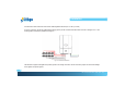
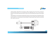
The SE inverter supports two common data interface standards, RS-232 and RS-485 that will be used to communicate to the remote computer
or terminal. Only one of the communication interfaces can work at a time. As shown in the figure 2.3.3.1, there are two RJ-45 connectors (RJ45-
L and RJ45-R) located on the bottom of the wiring box. The pin numbers of the RJ-45L and RJ-45R connectors and the corresponding signals
are described in the figure 2.3.3.2 below.
!
Fig 2.3.3.1
Positions of the communication ports
and termination switch
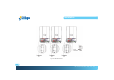
Fig 2.3.3.2 RJ-45 Pins and Signals
RJ45-L RJ45-R
Pin:
1. TXD (RS-232)
2. RXD (RS-232)
3. Not used
4. GND
5. GND
6. Not used
7. Data + (RS-485)
8. Data - (RS-485)
Pin:
1. Factory reserved
2. Factory reserved
3. 5V
4. GND
5. GND
6. 5V
7. Data + (RS-485)
8. Data - (RS-485)