
User's Manual


Page
4
EXHIBIT 5 FCC ID :
3.6 Self Test:
The keyboard microprocessor will perform a self test after power-up or after the host system signal the keyboard
to perform a software Reset.
The microprocessor will check its data memory locations, do a sum check internal ROM check and any
depressed keys.
If the self test is correct, the keyboard will transmit an ‘AA’ code, this will be the first transmission following a
Power-up condition.
If the self test is unsuccessful, then the keyboard will transmit a ‘FD/FC’ code. In either case, after the self test
check the keyboard will begin normal operation.
4. Connector and cable
There is a exits on lower casework for cable routing purpose. Cable is 4.5 feet in length, Shield and straight
with 6 pin mini-DIN connector. The keyboard is connected to HOST UNIT through a 6 pin DIN connector.
The connector and their signals is showed the following .
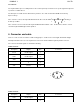
5-PIN connector
Description Signal Pins Connector
Clock +5V DC signal 1
Data +5V DC signal 2
GND 3
04
VCC +5V DC 5
6-PIN connector
Description Signal Pins Connector
Data +5V DC signal 1
2
1
54
2
3
1
54
2
3