
Installation manual
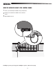
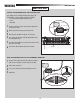
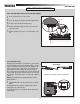
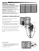
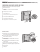
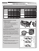
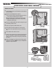

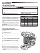
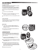
Table Of Contents

25
POWER WIRING (SOLAR PANELS) CONTINUED...
SET OP N
SET CLO E
MOVE
GATE
5
10
6
S C N S)
O EN
CLO E
TOP
AT CH RG NG
TE M VNG
CC WR O L
OD S
ST TUS
“ RE
D
O
E
SH
C OS
N E R
O
CC SS RY
P WER
ON SW
E P
BO RD
R
R
E A E
O E N
LM T
2
J 5
J15
+
BATT
+
DC
POWER
-
+
CONNECT BATTERIES
1
Locate the Charge plug on the control board and remove the transformer
wires from the inputs.
2
Remove the electrical housing from the control box:
1 Remove the wire ties from the electrical housing and remove the five
screws securing the electrical housing to the control box.
2
Remove the junction box cover and remove the bottom standoff.
3 Shift the electrical housing to the side and remove the ground nut
holding the ground wire in place.
3
Remove the two middle standoffs in the control box and cap the exposed
screws with the provided acorn nuts.
4
Cap the exposed ground screw with the third acorn nut.
5
Place the battery tray in the bottom right corner of the control box.
Ensure the wires are not pinched and routed to the side of the battery
tray.
6
Place the batteries in the control box as shown.
7
Connect the longer red wire from the J15 plug (new solar wire harness) to
the positive (+) terminal of one battery. Connect the longer black wire
from the J15 plug (new wire harness) to the negative (-) terminal of the
other battery.
8
Apply power by plugging the J15 plug (new solar wire harness) into the
J15 input on the control board. NOTE: You may see a small spark when
plugging the J15 plug into the board.
POWER WIRING (SOLAR PANELS)
WIRING
Red Wire (+)
Black Wire (-)
J15 Plug
(new wire harness Model
LA500SLRHARN)
Charge Plug with
Transformer Wires
Electrical Housing
Junction Box Cover
Bottom Standoff
Acorn Nuts
Battery Tray