
Installation manual
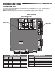
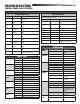

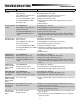

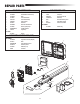
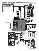
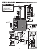
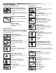
Table Of Contents
40
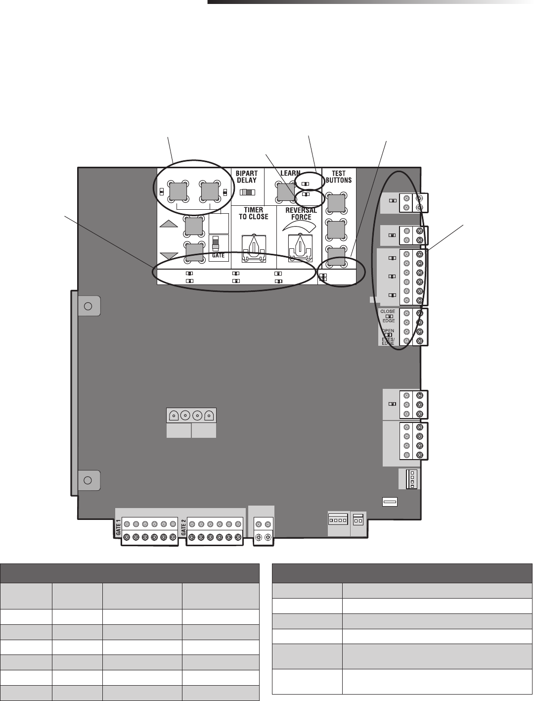
The control board is equipped with many LEDs that have a variety of functions. The control board LEDs indicate the status of the operator, assist with programming, and
diagnose potential problems with the operator.
NOTE: When cycling or disconnecting power (ac/dc) to the control board, it is recommended that you unplug the J15 and Solar/Charger plug.
CONTROL BOARD LEDS
TROUBLESHOOTING
SET OPEN
SET CLOSE
MOVE
GATE
OFF
5
10
60
180
MIN
MAX
(SECONDS)
OFF
ON
OPEN
CLOSE
STOP
INPUT POWER
BATT CHARGING
TIMER
GATE MOVING
BATT LOW
ACC PWR OVLD
DIAGNOSTIC
CODES
STATUS:
SBC
“FIRE
DEPT.”
OPEN
EXIT
SHADOW
CLOSE
EYES/
INTERRUPT
LOCK
N.O.
COM
N.C.
+ -
+ -
ACCESSORY
POWER
ON SW.
EXP.
BOARD
XMITTER
NETWORK
PRESS &
RELEASE
TO BEGIN
SETUP
CLASS 2 SUPPLY
24 VOLTS
1
LIMIT
2
- +
+ -
+ -
CHARGER
J15
+ -
BATT
- +
DC
POWER
ID RESET
ALARM
GROUND
BR GRN WT YE BLU RED
BR GRN WT YE BLU RED
STATUS LEDS
CONTROL BOARD LEDS
GREEN XMITTER LED
XMITTER LED EXPLANATION
OFF No remote control activity, normal operation.
ON Programming mode active.
ON (for 1 second) Recognized remote control signal.
ON (for a 1/4 of a
second)
Unrecognized remote control signal.
ON (8 blinks per
second)
Remote controls are being erased.
LIMIT SETUP LEDS
SET OPEN
LED
SET CLOSE
LED
OPERATOR MODE EXPLANATION
BLINKING BLINKING NORMAL MODE Limits are not set.
OFF OFF NORMAL MODE Limits are set.
BLINKING BLINKING LIMIT SETTING MODE Limits are not set.
BLINKING ON LIMIT SETTING MODE Open limit is not set.
ON BLINKING LIMIT SETTING MODE Close limit is not set.
ON ON LIMIT SETTING MODE Limits are set.
LIMIT SETUP LEDS
GREEN XMITTER LED
DIAGNOSTIC CODES LEDS
INPUT LEDS
YELLOW NETWORK LED