
Installation manual
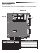
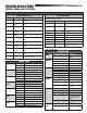

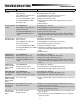

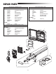
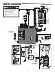
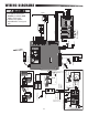
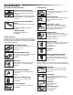
Table Of Contents
41
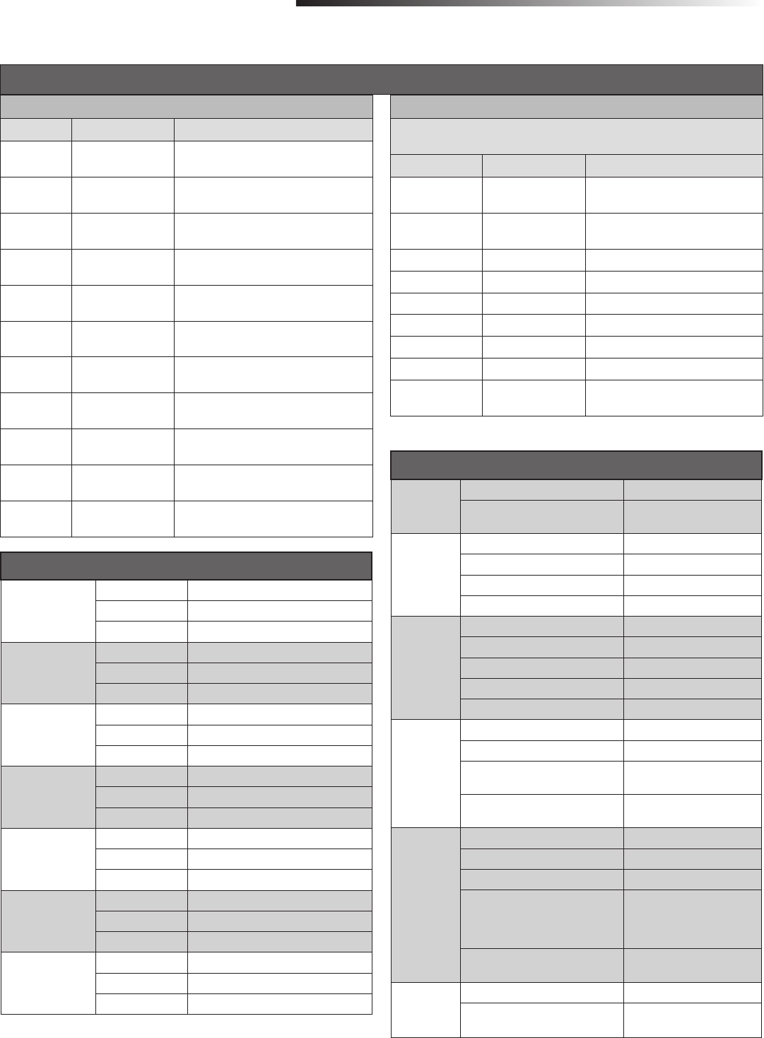
INPUT LEDS
OPEN INPUT OFF Input inactive
ON Input active
BLINK Input active on other operator
CLOSE INPUT OFF Input inactive
ON Input active
BLINK Input active on other operator
STOP INPUT OFF Input inactive
ON Input active
BLINK Input active on other operator
FIRE DEPT
INPUT
OFF Input inactive
ON Input active
BLINK Input active on other operator
SBC INPUT OFF Input inactive
ON Input active
BLINK Input active on other operator
OPEN SAFETY
INPUT
OFF Input inactive
ON Input active
BLINK Input active on other operator
CLOSE SAFETY
INPUT
OFF Input inactive
ON Input active
BLINK Input active on other operator
STATUS LEDS
INPUT
POWER
OFF OFF state
ON AC charger or Solar power
available
BATT
CHARGING
OFF Not charging
ON Trickle charge
FAST BLINK (2 blinks per second) High current charge
SLOW BLINK (1 blink every 2 seconds) Medium charge
TIMER OFF The timer is disabled
ON The timer is enabled
MEDIUM BLINK (1 blink per second) The timer is running
FAST BLINK (2 blinks per second) The timer is paused
FASTEST BLINK (8 blinks per second) The timer is cancelled
GATE
MOVING
OFF The gate is stopped
ON The gate is opening or closing
MEDIUM BLINK (1 blink per second) Operator is in E1 (single
entrapment)
FASTEST BLINK (8 blinks per second) The operator is in E2 (double
entrapment)
BATT LOW OFF No battery error
ON Battery low
MEDIUM BLINK (1 blink per second) Battery critically low
FAST BLINK (2 blinks per second) Battery disconnected error (seen
in solar application or using
plug in transformer motion is
inhibited)
FASTEST BLINK (8 blinks per second) Battery over voltage/over
current error
ACC PWR
OVLD
OFF OFF state
ON Accessory overload protector
opened
CONTROL BOARD LEDS
TROUBLESHOOTING
CONTROL BOARD LEDS CONTINUED...
YELLOW DIAGNOSTIC LED
# BLINKS MEANING CORRECTION
2 BLINKS ID resistor failure Check ID resistor wiring, clear limit settings and
reset limits
3 BLINKS Exceeded Maximum
Run Timer
Check gate travel, if necessary adjust force
setting
4 BLINKS Gate 1 disengaged Verify the release handle is engaged and
locked
5 BLINKS Gate 1 RPM
(obstruction)
Check for obstruction, if necessary adjust force
setting
6 BLINKS Gate 1 current
(obstruction)
Check for obstruction, if necessary adjust force
setting
7 BLINKS Gate 1 position failure Check gate travel, clear limit settings and reset
limits
8 BLINKS Gate 2 disengaged Verify the release handle is engaged and
locked
9 BLINKS Gate 2 RPM
(obstruction)
Check for obstruction, if necessary adjust force
setting
10 BLINKS Gate 2 current
(obstruction)
Check for obstruction, if necessary adjust force
setting
11 BLINKS Gate 2 position failure Check gate travel, clear limit settings and reset
limits
12 BLINKS Loop Error One of the loops is in error. Refer to the loop
detector to determine the error.
RED DIAGNOSTIC LED
BEFORE replacing the control board cycle the power first. If the problem persists, then
proceed with the appropriate correction.
# BLINKS MEANING CORRECTION
2 BLINKS Current Sense Motor control circuit fault, replace control
board
3 BLINKS FET Failure Motor control circuit fault, replace control
board
4 BLINKS RAM Failure Memory failure, replace control board
5 BLINKS Flash Memory Failure Memory failure, replace control board
6 BLINKS EEPROM Failure Memory failure, replace control board
7 BLINKS Watchdog Failure Controller failure, replace control board
8 BLINKS Brownout* Check power harness or line voltage
9 BLINKS Fail Control Board failure
10-15 BLINKS Software Failure Cycle power to the control board. If
continues replace control board.
DIAGNOSTIC CODES LEDS
* NOTE: After a brownout there is some delay before the system comes up. During this delay
the Amber LED will flash rapidly.