
Installation manual
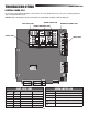
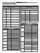

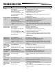

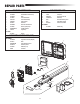
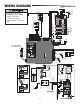
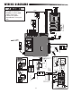
Table Of Contents

46
To protect against fire and electrocution:
• DISCONNECT power and battery BEFORE
installing or servicing operator.
For continued protection against fire:
• Replace ONLY with fuse of same type and
rating.
STANDARD CONTROL BOX
WIRING DIAGRAMS
Attach to Outlet
Metal Chassis
With a Single Screw
SET OPEN
SET CLOSE
MOVE
GATE
OFF
5
10
60
180
MIN
MAX
(SECONDS
OFF
ON
OPEN
CLOSE
STOP
NPUT POWER
BATT CHARG NG
T MER
GATE MOV NG
BATT LOW
ACC PWR OVLD
D AGNOST C
CODES
STATUS:
SBC
“F RE
DEPT”
OPEN
EX T
SHADOW
CLOSE
EYES/
NTERRUPT
LOCK
N O
COM
N C
+
+
ACCESSORY
POWER
ON SW
EXP
BOARD
XM TTER
NETWORK
PRE S &
RELEASE
TO BEG N
SETUP
LASS 2 UPP Y
4 VOL S
1
L M T
2
+
+
+ -
CHARGER
Photoelectric Sensors
Photoelectric Sensors
Edge
Edge
J15
Field Wiring
EXPANSION BOARD
Yellow
Blue
Black
Red
+
-
+
-
+ -
BATT
- +
DC
POWER
D RESET
ALARM
Piezo Alarm
White
Wh te
Purple
Reset Switch
Red
Black
GROUND
BR GRN WT YE BLU RED
BR GRN WT YE BLU RED
Loop Detector
Field Wiring
Wire Loop
Wire Loop
Wire Loop
Field Wiring
N.C.
Brown
Purple
Transformer 200 VA
+
-
-
-
Bridge Rectier
Wire Nut
Gray
Blue
12V 7AH Battery
Black
Red
12V 7AH Battery
To J15
Primary Operator
Secondary Operator
Black
Red
Yellow
White
Red
Orange
N
GND
GND
L
N
Input Power Connection
Input Power Connection
EMI FILTER/SURGE PROTECTION BOARD
L
Switch/5A Breaker
Tranformer Run Kit (Optional)
Accessory Power
Outlets
Attach to Metal Chassis
Black
Black
Red
White
Ground
Connect Outlets
to Transformer
Kit
LOCK
N O
COM
N C
Maglock
(Optional)
(not provided)
LOCK
N O
COM
N C
Solenoid Lock
(Optional)
(not provided)
GROUND
Attach to Outlet Metal Chassis
With a Single Screw
Two 12V Solar Panels in Series
+
-
-
+
Black
Red
Black
Red
Transformer
(Optional)
+
-
Blocking
Diode
Coaxial Antenna Cable
Antenna