
User's Manual

Doc: Silver Spring Networks - Confidential and Proprietary Page 2 of 4
2 Architecture
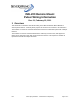
The Remote Mount IMU pulse input is compatible with a Form A (normally open) switch. The
voltage to the input is provided by an internal pull-up as shown in Figure 1. The voltage and
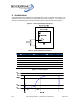
timing for a valid input pulse to the Remote Mount IMU is shown in Table 1 and Figure 2.
Figure 1 – Pulse Input Electrical Diagram
Table 1 – Pulse Electrical Parameters
Spec Nom. Min. Max.
V
BAT
2.1V 1.9V 2.14V
V
IL
-- -0.5V 0.36V
V
IH
-- 1.5V 2.3V
t
Fall
-- -- 10 ms
t
Low
-- 15 ms 100ms
t
Rise
-- -- 140 ms
t
Period
-- 500 ms --
Figure 2 – Pulse Diagram