
User's Manual

Doc: Silver Spring Networks - Confidential and Proprietary Page 3 of 4
2.1 Connection Definitions
The Remote Mount IMU has been tested with two devices to support current customer needs.
These devices are the Riotronics –PS4 model and the Mercury Corrector. Signal connections to
each of the devices are shown in Table 2.
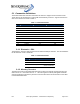
Table 2 – PCBA Connections
Pin IMU-300 Riotronics –PS4 Mercury Corrector
1 Pulse IN Ch. 1 Pulse Out Pulse Out Ch. A +
2 Ground Ground Ground
3 Pulse IN Ch. 2 N/C Pulse Out Ch. B +
4 Ground N/C N/C
5 Pulse IN Ch. 3 N/C Pulse Out Ch. A Corrected +
6 Ground N/C N/C
7 Pulse IN Ch. 4 N/C Pulse Out Ch. B Corrected +
8 Ground N/C N/C
9 Tamper+ Tamper Tamper +
10 Tamper- N/C N/C
2.1.1 Riotronics –PS4
The Riotronics –PS4 is a single channel form A switch with tamper detection. The wire definitions
for the Riotronics –PS4 is as follows:
Table 3 – PCBA Connections
Pin Signal Wire
1 Pulse Out Red
2 Ground Black
3
Tamper Bare wire
w/ wire end sheath
2.1.2 Mercury Corrector
The Mercury Corrector uses differential channels for each of the signals, meaning that there is a
Pulse Out Ch. A + and a Pulse Out Ch. A -. All of the negative or return path signals should be
connected together at the Mercury Corrector unit and connected to the Ground wire on the cable
to the Remote Mount IMU.