
user manual


12
SilverBoom 130
ELECTRICAL WIRING INSTALLATION
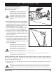
1. Route the lift’s long red positive (+) power wire (starting at the lift) through the interior of the vehicle
until you reach the automobile battery. See figure 12. Conceal the wire behind or under the interior
panels (there should be existing holes). Be certain that the wire is protected with a rubber grommet when
passing it through the metal panels and into the engine compartment. Inside the engine compartment,
secure the wire to the firewall and the inner fender with the supplied plastic wire ties. Use care not to cause
abrasions to the power wire. It is important to secure the power wire at various points along its run.
WARNING! The red positive (+) wire must be connected directly to the positive (+) battery
terminal.
2. Connect the short portion (with fuse) of the red positive (+) power wire to the positive (+) battery terminal.
3. Insert the end of the long portion of the red power wire into the yellow connector of the short portion
and crimp it securely. Once crimped, pull on the wire gently to ensure a good connection. Wrapping the
connector with electrical tape will help prevent moisture from corroding the connection.
III. INSTALLATION
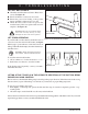
Figure 10. L-Base Cap
L-BASE CAP
PHILLIPS HEAD SCREW
10 MM
Figure 11. Fully Assembled Lift
L-BASE
UPPER POST
L-BASE CAP
MOTOR HOUSING
T-BAR
7. Place the L-base cap over the L-base and secure it with the supplied screws. See figure 10.
8. Reinstall the upper post.
9. Reinstall the motor housing and make adjustments as necessary.
The lift is now fully assembled. See figure 11.