
Specifications


Section 2
Fault Code Diagnostics
38
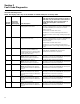
108 6C Shift lever error
ZF-FreedomLine shifter analog shift lever
(Freightliner and Sterling vehicles only)
First check all wiring harness connections between the
shift lever and the ZMTEC and the ZMTEC and the GS3.
If they look good (no damaged pins, correctly set home,
etc.), then do the following.
Check for continuity (0.0 to 0.5 ohms) between pins 1
and 8 of the shift lever harness connector (J10) and pin
G3 of the ZMTEC connector (J3). Check for continuity
between pin 3 of the shift lever harness connector (J10)
and ground. Check for continuity between pin 7 of the
shift lever harness connector (J10) and pin F1 of the
ZMTEC connector (J3). Check for continuity between pin
9 of the shift lever harness connector (J10) and pin E3 of
the ZMTEC connector (J3). Also check for shorts between
these circuits and all other pins in the wiring harness. If
these resistances check out okay and no short circuits
exist, replace the shift lever assembly. For diagnostic
procedures concerning the Freightliner SmartShift lever
and the push-button shift lever for International trucks,
contact the applicable OEM. For assistance, contact
OnTrac at 866-668-7221 and request a ZF-FreedomLine
transmission specialist.
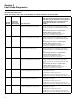
110 6E ZF CAN timeout Unplug the ZMTEC only and check for 58.0 to 62.0 ohms
resistance across pins D1 and D2 of the ZMTEC
connector (J3). Now remove the transmission wiring
harness and check for continuity (0.0 to 0.5 ohms)
between pin 3 of the TCU connector (J1), pin D1 of the
ZMTEC connector (J3), and pin A of the CAN terminator
connector (J8). Check for continuity between pin 6 of the
TCU connector (J1), pin D2 of the ZMTEC connector (J3),
and pin B of the CAN terminator connector (J8).
If any of these tests reveal issues with the wiring
harness, replace the wiring harness.
For assistance, contact OnTrac at 866-668-7221 and
request a ZF-FreedomLine transmission specialist.
114 72 Clutch engagement error
NOTE: The clutch engaged
unintentionally at a standstill with the
gear engaged.
Verify air supply into clutch actuator (system pressure
should be 110-130 psi) air supply within spec, replace
clutch actuator.
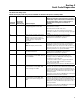
117 75 Error in clutch self-adjustment process
NOTE: The clutch is unable to cycle.
If error occurs immediately after engine startup, then
check the clutch engagement hardware for issues such
as a broken fork, jammed release bearing, failed release
bearing, broken clutch retaining clip, possible glazed
clutch disc, jammed clutch actuator rod, etc.). Address
any issues as necessary. If nothing is found, grease the
interface between the fork and the release bearing (this
includes the tips of the forks as well as the side walls of
the release bearing).
If clutch actuator does not move when engine is started,
replace clutch actuator.
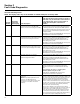
ISO Fault Code Diagnostics
NOTE: ISO display codes may not be available on vehicles built prior to January 2006.
ISO Fault
Identifier
ISO Display
Fault Codes
(J587 Display) Fault Description
Repair Instructions
NOTE: The following repair instructions pertain to
active faults only. For information and instructions
about inactive faults, please contact OnTrac at
866-668-7221 and request a transmission
specialist.