INSTALLATION MANUAL 6/11/2021 release 1
PRODUCT & INSTALLATION MANUAL Table of Contents 1) 2) 3) 4) 5) 6) 7) 8) 9) 10) 11) SYSTEM & INSTALLATION OVERVIEW ............................................................................................ 3 ESTIMATING REQUIRED SILVERMINE MATERIALS .................................................................... 4 TRANSPORTING, STORING & HANDLING......................................................................................... 4 RECOMMENDED TOOLS & EQUIPMENT.....................................
1) SYSTEM & INSTALLATION OVERVIEW INSTRUCTIONSa - This manual will guide you through every element of the installation process. Carefully read all installation instructions before starting your project, paying close attention to all safety precautions. The videos at www.SilvermineStone.com are a great resource for instructions and helpful hints for installation.
2) ESTIMATING REQUIRED SILVERMINE MATERIALS Silvermine‘s estimating tool is available on the Silvermine website (https://silverminestone.com) and has all of the logic necessary to calculate your project material needs built into it. Enter the project measurements and the tool will calculate the number of flats (regular and starter), corners (regular and starter), sills, under opening sills, starter strips, fasteners and flashing necessary to complete your project.
Pencil/marker Rubber Mallet 5-gallon buckets (for rinsing panels) Soft Nylon Brush Extension Cord(s) Screw gun T-Bevel/Angle Finder (for peaks only) Utility Knife Masonry drill bits o 1/8” (for pilot hole) o 5/16” (for counter sink hole) Staple Gun (for installation of vapor barrier and flashing) Hammer and roofing nails for installation of flashing (if necessary) Tin snips Caulk gun Other tools that may be needed Ladder(s) and or scaffolding Electric hand grinder (with OSHA-approved guard and a diamond w
• Walls must be sheathed with either 7/16" OSB or 1/2" plywood that is in good condition and properly fastened as per manufacturer’s instructions and building codes. • Wall framing must be designed to limit out-of-plane wall deflection to a minimum of L/240. • Structure must be able to handle stone panel weight of 15 lbs./sq ft exclusive of any other external loading (i.e., wind or seismic load).
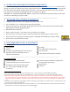
• FASTENER SPECIFICATIONS - For aluminum flashing, use only fasteners that meet the specifications below and drive them 90o to face of structure (See Figure 2) o Head Types: Pancake Head, Modified o Material: Quality Multiple-Coated Steel Truss Wafer Head, Washer Head or stainless steel o Size: #10x1-1/2” or longer o Threads/Inch: 12 or less, fully threaded o Head size: 12mm or larger o Head : shaft angle: 90° shaft.
• Note: Adhesive cannot be expected to hold if bonded directly to the house wrap or to SAF. The adhesive needs a material to which it can achieve a strong bond and make a sound mechanical connection to sheathing/framing such as non-paintedp, clean metal flashing or metal lath fastened securely to substrate and studs.
• Avoid cutting panels to a width less than 18 inches. This will help ensure at least one fastener can penetrate a stud. See Section 8 for fastening panels less than 18 inches in length. • When selecting stones to cut, keep in mind where the cut will be facing and what the cut end will butt against. Consider how the seam will look from all directions. Avoid corners, focal points, and facing high traffic sightlines for the cut end.
• Once this point has been determined, snap a level line for leveling board. The line represents the top back edge of the board. Note: It is helpful to continue marking level lines at 2-foot intervals. This allows visual confirmation courses are remaining level. • Ensure board is level and fasten sufficiently to hold panels as the initial course is completed. • Once the initial course is installed, REMOVE THE LEVELING BOARD. Note: if installing above an existing level trim board (e.g.
• Using a short level, ensure the panel is level and aligned with the adjacent corner or trim. Use a level on every panel and accessory to ensure the panels stay level from panel to panel and course-to-course. • Fasten the panel to the wall using Silvermine Stone approved screws (see Section 8). • Continue installing panels using the instructions above for guidance until you have completed the initial course or worked your way to an inside corner.
11) SUPPLEMENTAL FLASHING & TRANSITIONS Refer to - for this section. Step Flashing Defined Silvermine’s patented integrated flashing system is designed to form a shingle-like pattern, much like that of a shingled roof. In the case of roofs, continuous flashing against a sidewall is one way to install a roof, but it’s not the correct way. It may seem as if a single piece of flashing would offer more protection than many pieces of step flashing, but it doesn’t work that way.
• Adjust the pieces to fit snugly against the corner making the tightest joint possible • Hold pieces in place, ensure they are square and level in both directions, and fasten following the instructions (see Section 8).
• When used as a Wainscoting Cap, the 36” sill piece is installed directly on top of the last course of stone veneer panels. • Install sill before installing cladding material above. This will ensure the integrated flashing lays behind the cladding material above. • Apply an 8+ inch strip of approved SAF over the sill’s integrated flashing, covering all gaps and housewrap. • The sill is now prepared to be mated with transition cladding.
o Cut supplemental unpainted aluminum flashing to fit snuggly against the bottom edge of the opening, covering visible breathe holes. o Bend the sill flashing back on itself so the flashing can be seen below the sill when looking face on. o Trim the top of a modified panel to fit in the gap between the last full panel and the sill (this will hold the sill in place when fit). o Dry fit all parts to ensure tight fit, leaving a 3/8th inch gap between sill and opening.
• Fill gap with backer rod and sealant. • In cases where there is a frieze trim board already installed under the eave, install the stone as instructed in this section for under openings. • A tight eave is defined as an eave where there is no soffit that can be removed and the Silvermine stone panels must be modified to butt against the eave. Install the stone as instructed in this section for under openings.
• Install panels until course of stone panels is such that a full panel (stone portion) can no longer fit below where Accessory box will be installed. The aluminum will overlap your outline of the Accessory Box. Cut a hole in the flashing with tin snips so that electrical box will fit through the aluminum flashing. • Using SAF, flash around outlet box 12 inches on either side of and 8 inches above electrical box. • Install the next course until the panel reaches the edge of the Accessory Box.
• Apply a ¼ inch thick dashed line of adhesive along the top of the panels below the notched, partially modified panel prior to installing the notched panels. Leave 2” spaces between “dashes” for water to escape. • Step flash the panels on either side of the vent opening (See Flashing Vertical Transitions section). • Install the next stone course. When the vent is reached, cut a notch in the bottom corner of the panels so that the panel fits around the vent. Dry fit both panels to ensure proper fit.
13) DEALING WITH COMPLIMENTS Silvermine recommends the following approaches to dealing with the many compliments you will encounter following completion of your installation: • • • • • Be gracious - Don’t gloat that your property looks so great. Take credit for doing it yourself if you did - you did and it looks great, so pat yourself on the back. Ask for landscaping advice - it’s nice to be inclusive. Tell them it is Silvermine (thanks for the word of mouth advertising).
APPENDIX A - STONE ESTIMATION SHEET Rectangular dimensions (walls) Height Wall # Feet Length Inches Feet Inches Sill on top? 1 2 3 4 Large Openings, e.g., windows, doors, garage doors (areas not covered by stone) Height Opening # Feet Length Inches Feet Inches Sill on top? 1 2 3 4 5 6 CORNERS calculation Height Feet 1 2 3 4 5 6 Peak (non-rectangular) calculations Sq Feet 1 2 Buffer % 20 Inches Opening on ground (e.g.
APPENDIX B –DRAWINGS Fig.
APPENDIX B - INSTALLATION DRAWINGS Fig. B-2 Initial Course Over Foundation Wall Base HOUSEWRAP STONE PANEL PANEL FLASHING 8+" HIGH UNPAINTED ALUMINUM FLASHING SHEATHING ADHESIVE STONE PANEL 1" MIN BOTTOM OF STONE PANEL 2" MIN. AT PAVING 4" MIN. AT GRADE SLOPE GRADE 2% MIN.
APPENDIX B - INSTALLATION DRAWINGS Fig. B-3 Initial Course Over Water Table Trim STONE PANEL STONE PANEL STONE PANEL 8+" HIGH UNPAINTED ALUMINUM FLASHING ADHESIVE GSM TRIM FLASHING WITH 3" MINUMUM VERTICAL LEG WATER TABLE TRIM SHEATHING HOUSEWRAP 1" MIN BOTTOM OF WATER TABLE TRIM 2" MIN. AT PAVING 4" MIN. AT GRADE SLOPE GRADE 2% MIN.
APPENDIX B - INSTALLATION DRAWINGS Fig. B-4 Outside Corner w/ Step Flashing HOUSE WRAP SHEATHING 18" CORNER PANEL PANEL FLASHING PANEL FLASHING FROM COURSE BELOW SAF OVERLAP PANEL FLASHING 2" MIN. SAF OVERLAP COURSE BELOW PANEL FLASHING 2" MIN.
APPENDIX B - INSTALLATION DRAWINGS Fig. B-5 Inside Corner w/ Step Flashing PANEL FLASHING FROM COURSE BELOW SAF OVERLAP COURSE BELOW PANEL FLASHING 2" MIN. PANEL FLASHING PANELS - MITERED 45 DEGREES SAF OVERLAP PANEL FLASHING 2" MIN.
APPENDIX B - INSTALLATION DRAWINGS Fig. B-6 Vertical Transition w/ Step Flashing BLOCKING AT PANEL EDGE SEALANT HOUSEWRAP PANEL SAF 8" TALL MINIMUM.
APPENDIX B - INSTALLATION DRAWINGS Fig. B–7 Panels Below Siding HOUSEWRAP SEE SIDING MFR. INSTALLATION INSTRUCTIONS WRB PER SIDING MFR. INSTALLATION INSTRUCTIONS SAF BLOCKING FOR GSM FLASHING FINISH SIDING SEALANT LEAVE GAP AT BASE OF SIDING FOR WEEP GSM FLASHING WITH 3" MIN.
APPENDIX B - INSTALLATION DRAWINGS Fig. B–8 Panels Below Trim HOUSEWRAP SEE SIDING MFR. INSTALLATION INSTRUCTIONS FINISH SIDING WRB PER SIDING MFR. INSTALLATION INSTRUCTIONS SAF SEALANT LEAVE GAP AT BASE OF SIDING FOR WEEP BLOCKING FOR GSM FLASHING GSM FLASHING WITH 3" MIN.
APPENDIX B - INSTALLATION DRAWINGS Fig. B–9 Sills Below Siding HOUSEWRAP SEE SIDING MFR. INSTALLATION INSTRUCTIONS WRB PER SIDING MFR.
APPENDIX B - INSTALLATION DRAWINGS Fig. B-10 Panels/Sills Below Openings w/ Removable Trim OPENING SEALANT BLOCKING FOR GSM FLASHING REMOVABLE TRIM SAF GSM FLASHING WITH 3" MIN.
APPENDIX B - INSTALLATION DRAWINGS Fig. B-11 Sills Below Window w/out Removable Trim ALUMINUM OR VINYL WINDOW FRAME PROFILE - MAY VARY REFER TO MFR.
APPENDIX B - INSTALLATION DRAWINGS Fig. B-12 Panels Under Fixed Trim FIXED HORIZONTAL TRIM (i.e. FRIEZE BOARD, TITE ROOF, etc.) BACKER ROD AND SEALANT ADHESIVE GSM FLASHING WITH 3" MIN.
APPENDIX B - INSTALLATION DRAWINGS Fig.
APPENDIX B - INSTALATION DRAWINGS Fig.
APPENDIX B - INSTALATION DRAWINGS Fig.
APPENDIX B - INSTALATION DRAWINGS Fig.