INSTALLATION MANUAL 1
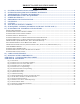
PRODUCT & INSTALLATION MANUAL Table of Contents 1) 2) 3) 4) 5) 6) 7) 8) 9) 10) 11) SYSTEM & INSTALLATION OVERVIEW ............................................................................................ 3 ESTIMATING REQUIRED SILVERMINE MATERIALS .................................................................... 4 TRANSPORTING, STORING & HANDLING......................................................................................... 4 RECOMMENDED TOOLS & EQUIPMENT ....................................
1) SYSTEM & INSTALLATION OVERVIEW INSTRUCTIONSa - This manual will guide you through every element of the installation process. Carefully read all installation instructions before starting your project, paying close attention to all safety precautions. The videos at www.SilvermineStone.com are a great resource for instructions and helpful hints for installation.
2) ESTIMATING REQUIRED SILVERMINE MATERIALS Silvermine‘s estimating tool is available on the Silvermine website (https://silverminestone.com) and has all of the logic necessary to calculate your project material needs built into it. Enter the project measurements and the tool will calculate the number of flats (regular and starter), corners (regular and starter), sills, under opening sills, starter strips, fasteners and flashing necessary to complete your project.
Masonry drill bits o 1/8” (for pilot hole) o 5/16” (for counter sink hole) Staple Gun (for installation of vapor barrier and flashing) Hammer and roofing nails for installation of flashing (if necessary) Tin snips Caulk gun Pencil/marker Rubber Mallet 5-gallon buckets (for rinsing panels) Soft Nylon Brush Extension Cord(s) Screw gun T-Bevel/Angle Finder (for peaks only) Utility Knife Other tools that may be needed Ladder(s) and or scaffolding Electric hand grinder (with OSHA
• Walls must be sheathed with either 7/16" OSB or 1/2" plywood that is in good condition and properly fastened as per manufacturer’s instructions and building codes. • Wall framing must be designed to limit out-of-plane wall deflection to a minimum of L/240. • Structure must be able to handle stone panel weight of 15 lbs./sq ft exclusive of any other external loading (i.e., wind or seismic load).
• Install fasteners at least 1 inch above the top edge of the panel to avoid water penetration. Drive fastener flush to the flashing/substrate layer. DO NOT overdrive fasteners as this can damage flashing. • Each panel should have at least 1 fastener driven into a stud. Panels longer than 16 inches should have at least 3 fasteners and panels less than 16 inches should have at least 2 fasteners.
Fastening Sills • Apply a 3/8 inch thick, quarter sized dollops of construction adhesive (every 6 to 8 inches) to the aluminum flashing the sill will cover 1-2 inches above the top edge of the panel beneath. • Apply a 1/4 inch thick dashed line of adhesive along the horizontal and vertical edge of the panels that will abut of the modified piece leaving 2 inches between “dashes” to allow water to escape.
• Use a continuous rim diamond saw blade circular saw rather than a segmented blade for cutting Silvermine. Segmented blades can cause cracking and chipping of panels. • Mark the stone panel where it will be cut. • Place panel face up on the saw table. • Using circular saw to cut panels, the blade should pass though the panel slowly, to avoid cracking. • Dust from cutting will leave a chalky appearance if not removed.
Initial Flashing (CRITICAL) • Each initial course will require flashing which must be a minimum of 8 inches tall. This the first layer of “shingling” and needs to extend at least 2 inches above the initial course of stone (thus the need for 8 inchwide uncoated aluminum coil flashing). • A drip cap/head flashing is required for most horizontal transitions. An effective drip cap for this application is a properly fastened 26-gauge metal (minimum) cap with a back leg at least 4 inches tall.
10) SUBSEQUENT COURSES (WORKING YOUR WAY UP THE WALL) Remember, install outside corners on the course you are working before installing panels. Alternate left and right corner pairs as you work your way up the wall. This helps prevent the alignment of vertical seams and maintain the necessary 6 inch offset (See Figure 3). Stair Stepping Corners and flats can be built up in a stair step fashion once the initial course of stone has been installed (See Figure 4).
onto the shingle. Even if one piece of step flashing fails, the flashing and shingle below will start the process over again. Step flashing is the process of applying a shingle, then flashing the edge/transition, applying the next course of shingles above it, then flashing the edge/transition and repeating the process. There are many articles on step flashing roofs. The concept for Silvermine is the same with respect to all vertical (e.g., across courses) transitions.
Flashing Vertical Transitions Vertical transitions occur anywhere Silvermine Stone products meet another material’s vertical edge. These edges must be flashed one course at a time. Use Fig. B-6 Vertical Transition w/ Step Flashing in conjunction with these instructions. When the vertical transition interrupts the initial course as doors often do, the seam where the initial flashing adjoins the joint between the sheathing and the vertical transition material must be sealed. See Section 12 for instructions.
• Note: If this is a remodel, and the existing cladding alone is an adequate substrate for stone veneer application, prep entire wall for cladding (check local building code), apply stone as wainscoting, properly flash, and install new cladding above. • Warning: Failure to properly flash between the cladding and the sill/stone below will void warranty and may result in foundation and structural damage. Under Openings (Trim removable, Sills or Panels Below) Use Fig.
• Bed the top edge of supplemental unpainted aluminum flashing into sealant and fasten securely with Silvermine’s approved application screws. • Leave 3/8" gap between sill and window frame. • Apply 3/8 inch thick, quarter sized dollops of construction adhesive (every 6 to 8 inches) to the aluminum flashing behind the sill. • Position sill and fasten integrated flashing to wall under sill (see drawing).
Over Trimmed Openings Use Fig. B-13 Initial Course Above Trimmed Openings in conjunction with these instructions. • Install drip cap over opening. • Once your courses on either side of the opening reach the point just below the opening and are step flashed on the vertical transition, apply SAF above the opening. • For the course that intersects with the opening, the bottom of the course will, in all probability, not align perfectly with the top of the opening.
• Place the Accessory Box in position but do not fasten. • Install the next stone in the course. • Remove Accessory Box and apply SAF the across the aluminum of the two stones on either side of the Accessory Box. • Install the Accessory Box. o Apply a 1/4 inch thick dashed line of adhesive along the top of the stone(s) the Accessory Box will be set on and along the edge of the stones to the left and right of the Accessory Box, leaving 2” spaces between “dashes” to allow water to escape.
12) CARE & MAINTENANCE Proper care and maintenance will ensure your investment looks as good in 20 years as did the day it was installed. Regular Cleaning • Use soap and water with a nylon bristle brush to remove dirt. • DO NOT POWERWASH - Power washing can remove the coloring from the stone. • DO NOT CLEAN WITH HARSH CHEMICALS OR ACID PRODUCTS. Avoid Salt and De-Icing Chemicals Silvermine products are not warranted against damage caused by salt or de-icing chemicals.
APPENDIX A - STONE ESTIMATION SHEET Rectangular dimensions (walls) Height Wall # Feet Length Inches Feet Inches Sill on top? 1 2 3 4 Large Openings, e.g., windows, doors, garage doors (areas not covered by stone) Height Opening # Feet Length Inches Feet Inches Sill on top? 1 2 3 4 5 6 CORNERS calculation Height Feet 1 2 3 4 5 6 Peak (non-rectangular) calculations Sq Feet 1 2 Buffer % 19 Inches Opening on ground (e.g.
APPENDIX B –DRAWINGS Fig.
APPENDIX B - INSTALLATION DRAWINGS Fig. B-2 Initial Course Over Foundation Wall Base HOUSEWRAP STONE PANEL PANEL FLASHING 8+" HIGH UNPAINTED ALUMINUM FLASHING SHEATHING ADHESIVE STONE PANEL 1" MIN BOTTOM OF STONE PANEL 2" MIN. AT PAVING 4" MIN. AT GRADE SLOPE GRADE 2% MIN.
APPENDIX B - INSTALLATION DRAWINGS Fig. B-3 Initial Course Over Water Table Trim STONE PANEL STONE PANEL STONE PANEL 8+" HIGH UNPAINTED ALUMINUM FLASHING ADHESIVE GSM TRIM FLASHING WITH 3" MINUMUM VERTICAL LEG WATER TABLE TRIM SHEATHING HOUSEWRAP 1" MIN BOTTOM OF WATER TABLE TRIM 2" MIN. AT PAVING 4" MIN. AT GRADE SLOPE GRADE 2% MIN.
APPENDIX B - INSTALLATION DRAWINGS Fig. B-4 Outside Corner w/ Step Flashing HOUSE WRAP SHEATHING 18" CORNER PANEL PANEL FLASHING PANEL FLASHING FROM COURSE BELOW SAF OVERLAP PANEL FLASHING 2" MIN. SAF OVERLAP COURSE BELOW PANEL FLASHING 2" MIN.
APPENDIX B - INSTALLATION DRAWINGS Fig. B-5 Inside Corner w/ Step Flashing PANEL FLASHING FROM COURSE BELOW SAF OVERLAP COURSE BELOW PANEL FLASHING 2" MIN. PANEL FLASHING PANELS - MITERED 45 DEGREES SAF OVERLAP PANEL FLASHING 2" MIN.
APPENDIX B - INSTALLATION DRAWINGS Fig. B-6 Vertical Transition w/ Step Flashing BLOCKING AT PANEL EDGE SEALANT HOUSEWRAP PANEL SAF 8" TALL MINIMUM.
APPENDIX B - INSTALLATION DRAWINGS Fig. B–7 Panels Below Siding HOUSEWRAP SEE SIDING MFR. INSTALLATION INSTRUCTIONS WRB PER SIDING MFR. INSTALLATION INSTRUCTIONS SAF BLOCKING FOR GSM FLASHING FINISH SIDING SEALANT LEAVE GAP AT BASE OF SIDING FOR WEEP GSM FLASHING WITH 3" MIN.
APPENDIX B - INSTALLATION DRAWINGS Fig. B–8 Panels Below Trim HOUSEWRAP SEE SIDING MFR. INSTALLATION INSTRUCTIONS FINISH SIDING WRB PER SIDING MFR. INSTALLATION INSTRUCTIONS SAF SEALANT LEAVE GAP AT BASE OF SIDING FOR WEEP BLOCKING FOR GSM FLASHING GSM FLASHING WITH 3" MIN.
APPENDIX B - INSTALLATION DRAWINGS Fig. B–9 Sills Below Siding HOUSEWRAP SEE SIDING MFR. INSTALLATION INSTRUCTIONS WRB PER SIDING MFR.
APPENDIX B - INSTALLATION DRAWINGS Fig. B-10 Panels/Sills Below Openings w/ Removable Trim OPENING SEALANT BLOCKING FOR GSM FLASHING REMOVABLE TRIM SAF GSM FLASHING WITH 3" MIN.
APPENDIX B - INSTALLATION DRAWINGS Fig. B-11 Sills Below Window w/out Removable Trim ALUMINUM OR VINYL WINDOW FRAME PROFILE - MAY VARY REFER TO MFR.
APPENDIX B - INSTALLATION DRAWINGS Fig. B-12 Panels Under Fixed Trim FIXED HORIZONTAL TRIM (i.e. FRIEZE BOARD, TITE ROOF, etc.) BACKER ROD AND SEALANT ADHESIVE GSM FLASHING WITH 3" MIN.
APPENDIX B - INSTALLATION DRAWINGS Fig.
APPENDIX B - INSTALATION DRAWINGS Fig.
APPENDIX B - INSTALATION DRAWINGS Fig.
APPENDIX B - INSTALATION DRAWINGS Fig.