FORTRESS SERIES FT02 MANUAL
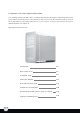
Installation and system optimization guide: The following manual and guides were carefully prepared by the SilverStone engineering team to help you maximize the potential of your SilverStone product. Please keep this manual for future reference when upgrading or performing maintenance on your system. A copy of this manual can also be downloaded from our website at: http://www.silverstonetek.com 1 Specification P.2 Disassemble chart P.3 Installation guide P.4 Connector definition P.
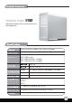
FORTRESS SERIES FT02 Advancing computer chassis construction and thermodynamics 4.5mm aluminum unibody frame, 0.8mm steel body SSI CEB, ATX (maximum 12” x 11”), Micro ATX Model No. SST-FT02B (black) SST-FT02S (silver) SST-FT02B-W (black + window) SST-FT02S-W (silver + window) 5.25" x 5 3.5" x 5 , 2.5” x1 Bottom 3 x 180mm intake fan 700/1000rpm, 18/27dBA Top 1 x 120mm exhaust, 1200rpm, 19dBA 7 USB2.
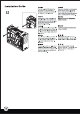
TOP COVER LEFT SIDE PANEL 18032 FAN SWICTH x 3 PSU FILTER PS2 PSU(OPTION) 12025 FAN ATX MB(OPTION) FRONT I/O 18032 FAN GUARD x 2 SILVERSTONETEK CP05 18032 FAN x 3 18032 FAN BRACKET x 2 5.25” DRIVE BAY x 5 3.5” HDD Tray 3.5” DRIVE BAY x 5 RIGHT SIDE PANEL-W USB2.0 CONNECTOR USB+5V LP- SCREW A SECURE 5.
lnstallation Guide Before you begin, please make sure that you (1) have all components collected (2) check that all components do not have compatibility problems with each other or with the case (3) if possible, assemble the components outside the case first to make sure they are working (4) keep the motherboard manual ready for reference during installation.
lnstallation Guide 4 A B C 4. Install PSU into the case as shown (two orientations are available in A or B), use screw C to secure the PSU 4.5. Route the PSU strap around the PSU and through to the corresponding hole on the motherboard tray to tighten the PSU 4. Installieren Sie das Netzteil wie dargestellt im Gehäuse (in A oder B sind zwei Ausrichtungen verfügbar), befestigen Sie das Netzteil mit Schraube C. 4.5.
lnstallation Guide 5 1 2 3 Take the included PSU holder from the accessory box and secure it with screw C to the case Выньте из коробки с аксессуарами прилагаемый держатель блока питания и привинтите его к корпусу с помощью шурупа С. Nehmen Sie die mitgelieferte Netzteilhalterung aus dem Zubehörkarton, sichern Sie diese mit Schraube C am Gehäuse.
lnstallation Guide 7 Push the 5.25” tool-less buttons to “unlock” position,then insert an optical drive or other 5.25” device into the case and align its bezel to the front panel С помощью отвертки удалите стальные пластины на отсеке для 5,25-дюймового дисковода, затем нажмите безвинтовые кнопки отсека, приведя их в положение "unlock". Drücken Sie die 5,25-Zoll-Knöpfe (kein Werkzeug erforderlich) in die „unlocked“ (entsperrt)-Position.
lnstallation Guide 9 Remove the hard drive tray as shown Выньте корзину для жесткого диска, как показано на рисунке. Nehmen Sie den Festplatteneinschub wie abgebildet heraus. 請依圖示將硬碟托盤取出。 Retirez le support à disques durs comme montré 请依图标将硬盘托盘取出。 Quite la bandeja para discos duros como se muestra 図のようにハードディスクドライブト レイを取り外します。 Rimuovere il cestello dell’hard disk come mostrato 하드 드라이브 트레이를 그림과 같이 제거합니다.
lnstallation Guide 11 Insert the completed hard drive tray back into the case (additional CP05 adapters can be purchased separately to make all SATA hard drives hot-swappable) Вставьте корзину с жестким диском в корпус (приобретите дополнительные адаптеры CP05, чтобы получить возможность горячего подключения жестких дисков SATA). Setzen Sie den Einschub mit Festplatte wieder in das Gehäuse ein. (Mit separat erhältlichen CP05-Adaptern können Sie sämtliche SATA-Festplatten für Hot-Swapping vorbereiten.
lnstallation Guide 13 Use screw A to secure the 2.5” hard drive to the bracket С помощью шурупа A закрепите 2,5-дюймовый жесткий диск в кронштейне. Sichern Sie die 2,5-Zoll-Festplatte mit Schraube A an der Halterung. 請依圖示用SCREW A,將2.5寸硬碟鎖固於 2.5寸硬碟架。 Utilisez une vis de type A pour fixer le disque dur 2.5” dans son casier 请依图标用SCREW A,将2.5寸硬盘锁固于 2.5寸硬盘架。 Use el tornillo A para fijar el disco duro de 2,5” al bracket 2.
lnstallation Guide 15 Insert all standoffs to corresponding holes on the motherboard tray as required by your motherboard, then place the motherboard on the standoffs and secure it with screw C 2 2 Вставьте все опоры в соответствующие отверстия лотка для материнской платы, затем поместите материнскую плату на опоры и закрепите шурупом С.
lnstallation Guide 17 After all wires and cables are connected and routed, place the side panels back onto the case and secure with thumb screws removed from step 2 После подключения всех проводов и кабелей верните на место боковые панели корпуса и закрепите винтами с рифленой головкой, открученными на этапе 2.
Connector definition (1) Front panel connector installation Power switch and reset switch installation guide: Please refer to the motherboard manuals for the motherboard’s “Front Panel Connector” or “System Panel Connector” pin definition. Power switch and reset switch have no polarity, so they can be connected in any orientation.
Front I/O connector guide Below are the front I/O connectors pin definition, please also check your motherboard manual to cross reference with motherboard’s front I/O pin headers. SilverStone’s I/O connectors are in block type to simplify installation. Nachstehend finden Sie die Pinbelegung der vorderen E/A-Anschlüsse; bitte gleichen Sie zudem das Handbuch Ihres Motherboards mit den vorderen E/A-Pinzuweisungen ab. SilverStones E/A-Anschlüsse befinden sich zur Vereinfachung der Installation in Blockart.
For liquid cooling, the maximum thickness allowed for radiator is 30mm when 10.5” expansion cards are installed and 60mm when 9” cards are installed. 1 Please remove 180mm fan filters as shown then remove the four 3*8 screws holding the 180mm fan bracket Снимите фильтры 180-мм вентилятора, как показано на рисунке, затем открутите шесть шурупов 3*8, удерживающих кронштейн вентилятора.
3 Remove 180mm fan bracket from the case then unscrew the eight screws holding the fan grille to the fan Выньте из корпуса кронштейн 180-мм вентилятора, затем открутите двенадцать шурупов, с помощью которых решетка крепится к вентилятору. 請依圖示抽出180風扇架, Entfernen Sie die Halterung des 180 mm-Lüfters vom Gehäuse, lösen 並鬆開8顆鎖固180風扇護網的螺絲。 Sie anschließend die acht Schrauben, die das Lüftungsgitter am Lüfter halten.
5 Secure the radiator onto the fans as shown Закрепите радиатор поверх вентиляторов, как показано на рисунке. Befestigen Sie den Kühler wie dargestellt an den Lüftern. 請依圖示將水冷排鎖固於風扇上。 Fixer le radiateur sur les ventilateurs comme montré 请依图示将水冷排锁固于风扇上。 Fije el disipador a los ventiladores como se muestra 図のようにラジエターをファンに固定 します。 Accoppiare il radiator alle ventole come mostrato. 그림과 같이 라디에이이터를 팬에 고정시킵니다.
7 Insert fan filters back into the fan bracket, please make sure the filters are in the correct orientation Вставьте фильтры вентилятора обратно в кронштейн вентилятора. Убедитесь, что фильтры правильно ориентированы. Stecken Sie die Lüfterfilter wieder in die Lüfterhalterung; achten Sie auf die korrekte Ausrichtung der Filter.
Component size limitations The FORTRESS FT02 was designed to accommodate oversize components, but we still recommend to refer to the following dimension guidelines: Das FORTRESS FT02 wurde so entworfen, dass es übergroße Komponenten aufnehmen kann; dennoch empfehlen wir die Einhaltung der folgenden Abmessungsrichtlinien: Le FORTRESS FT02 a été conçu pour accueillir des composants surdimensionnés, mais nous recommandons de toujours vous référer aux dimensions maximales suivantes: La Fortress FT02 fue diseñad
Graphic card/expansion card length limitation FT02 can support 12” consumer level graphics cards. Graphic card length reference: NVIDIA GeForce GTX260/275/280/285/295 - 10.5“ NVIDIA GeForce 9800GTX/9800GTX+ - 10.5“ AMD Radeon HD 4870X2 - 10.5 " NVIDIA Geforce GTS250 - 9” NVIDIA GeForce 9800GT/9600GT/GTO - 9" AMD Radeon HD 4890/4870/4850 - 9 " AMD Radeon HD 4770 – 8.
Standard SSI-CEB server motherboard can fit inside FT02 and mount its Xeon coolers to the motherboard tray Obwohl der FORTRESS FT02 nicht zur Verwendung von Extended-ATX-Motherboards entworfen wurde, ermöglicht der Platz im Gehäuseinneren die Installation eines Motherboards mit einer Breite von bis zu 28 cm. Hochmoderne Motherboards, wie z. B. ASUS’ Rampage II Extreme (27 cm) und EVGAs X58 SLI Classified (26,4 cm), sind breiter als die Standard-ATX-Motherboards von 24,4 cm.
FT02雖然尚未支援到E-ATX主機板,但是內部的空間允許最大寬度到11”的主機板。因此我們的主機板螺柱設計到支援SSI-CEB規格的雙CPU主 機板。而一般玩家級ATX主機板也有像ASUS Rampage II Extreme或EVGA X58 SLI Classified深度達到10.6”,超過正常9.6”的尺寸。一般ATX 機殼是不一定能安裝的。而FT02是可以正常支援沒問題的。 FT02虽然尚未支持到E-ATX主机板,但是内部的空间允许最大宽度到11”的主机板。因此我们的主机板螺柱设计到支持SSI-CEB规格的双CPU主 机板。而一般玩家级ATX主机板也有像ASUS Rampage II Extreme或EVGA X58 SLI Classified深度达到10.6”,超过正常9.
Top cover limitation 70mm The gap between I/O and top cover is 70mm Acceptable connector Unacceptable connector 24
Recommended cooling device setup and selection If you are installing a tower-style CPU cooler, we recommend that the CPU fan blows upward to work with FT02’s overall airflow Если вы устанавливаете башенный кулер ЦП, то мы рекомендуем установить его таким образом, чтобы воздушный поток вентилятора ЦП был направлен вверх и совпадал с общим направлением воздушного потока внутри корпуса FT02.
Cable routing There are hooks behind the motherboard tray for using cable straps in routing cables. За лотком для материнской платы находятся крюки, за которые цепляются фиксаторы кабелей при их прокладке внутри корпуса. Hinter dem Motherboard-Einschub 我們有在機殼正背面安置可以容納束線帶 befinden sich Haken, die der 的凸橋,請依指示將適當的線材綁在適當 Verwendung von Kabelbändern dienen.
Le tre ventole principali da 180mm di FT02 sono regolabili secondo due velocità, 700 o 1000rpm. Regolare quindi a 700rpm se si desidera la massima silenziosità di esercizio, a 1000rpm per massimizzare le prestazioni di raffreddamento.
Upgrade and maintenance (1)Fan removal guide If you need to replace, clean, or upgrade the fan, please follow the steps below 1 Please remove 180mm fan filters as Снимите фильтры 180-мм вентилятора, shown then remove the six 3*8 screws как показано на рисунке, затем открутите holding the 180mm fan bracket шесть шурупов 3*8, удерживающих кронштейн вентилятора.
3 Remove 180mm fan bracket from the Выньте из корпуса кронштейн 180-мм case then unscrew the twelve screws вентилятора, затем открутите holding the fan grille to the fan двенадцать шурупов, с помощью которых решетка крепится к вентилятору. Entfernen Sie die Halterung des 䂟ձ೪⼎ᢑߎ 乼ᶊ 180 mm-Lüfters vom Gehäuse, lösen Sie anschließend die zwölf Schrauben, die das Lüftungsgitter am Lüfter halten.
An example of a GPU cooler that is filled with dust and has lost most of its cooling performance FT02’s positive air pressure design is an effective configuration that will reduce dust buildup inside the case. Small air particles or lint will accumulate over time on FT02’s intake filters instead of on the components inside the case.
A Power supply filter removal guide: Please press on the two power supply filter tabs as shown in illustration ”1”, then pull them out to remove filter from the chassis as shown in illustration ”2.” Инструкция по демонтажу фильтра БП: нажмите на два стопора фильтра блока питания, как показано на рисунке 1, затем потяните за них и выньте фильтр из корпуса, как показано на рисунке 2.
ClearCMOS FT02 supports SST-CLEARCMOS installation on a designated part of the case, please see example below: Das FT02 unterstützt die SST-CLEARCMOS-Installation an einem dazu vorgesehenen Teil des Gehäuses; bitte halten Sie sich an das nachs tehende Beispiel: Le FT02 est compatible avec l'installation du SST-CLEARCMOS dans une partie spéciale du boîtier, voici un exemple ci-dessous: La FT02 acepta la instalación de la SST-CLEARCMOS en cierta parte de la caja, por favor vea el siguiente ejemplo: FT02
SATA hot-swap You can purchase additional CP05 adapters to enable SATA hard drive hot-swap. There is already one included in the case, with four more slots available for further installation. Please note the following points if you decide to utilize the hot-swap functionality: A. If you need to swap hard drives while running an operating system (hot-swap), you need to make sure the SATA chipset (or motherboard s outhbridge) used to connect to hard drives has proper support and driver to do so.
E’ possible acquistare separatamente adattatori CP05 per abilitare la funzione hot-swap per gli hard disk SATA. Uno è compreso negli accessori del case, ma sono presenti altri quattro slot che possono essere utilizzati con l’adattatore in oggetto. Leggere con attenzione i seguenti punti se si desidera utilizzare la funzionalità hot-swap. A.
Issue date: September, 2009 G11210830