GD08
Installation and system optimization guide: The following manual and guides were carefully prepared by the SilverStone engineering team to help you maximize the potential of your SilverStone product. Please keep this manual for future reference when upgrading or performing maintenance on your system. A copy of this manual can also be downloaded from our website at: http://www.silverstonetek.com 1 Specification P.2 Disassemble chart P.3 Installation guide P.4 Connector definition P.
GD 08 Amazing home theater server case with incredible storage and cooling capacity Material Aluminum front panel, steel body Model SST-GD08B (black) Motherboard SSI EEB, SSI CEB, Extended ATX, ATX, Micro ATX *1 Drive Bay Exposed 5.25" x 2 (support optical drive only) Internal 3.5" x 8, 2.
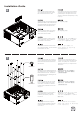
2.5” DRIVE BAY x 2 5.25” DRIVE BAY x 2 3.5” DRIVE BAY x 4 3.5” DRIVE BAY x 3 TOP COVER 12025 FAN x 1 (OPTION) RIGHT SIDE FILTER x 1 8025 FAN x 2 (OPTION) EXPANSION SLOTS x 8 3.5” DRIVE BAY x 1 ATX MB (OPTION) 12025 FAN x 1 PS2 PSU (OPTION) USB 3.0 x 2 + SPK + MIC LEFT SIDE FILTER x 2 RESET BUTTON POWER BUTTON 12025 FAN x 2 BOTTOM SIDE FILTER x 2 12025 FAN x 1 (OPTION) SCREW A Secure 5.25” drives (right cage) SCREW B Secure 3.5” hard drive tray SCREW C Secure motherboard, PSU, 3.
lnstallation Guide Before you begin, please make sure that you (1) have all components collected (2) check that all components do not have compatibility problems with each other or with the case (3) if possible, assemble the components outside the case first to make sure they are working (4) keep the motherboard manual ready for reference during installation (5) prepare a Philips screwdriver 1 Loosen two screws from the rear of the chassis then remove the top cover.
lnstallation Guide PSU Fan outward facing 3 Insert the power supply from the top, if the power supply has a built-in 120mm fan or larger, we recommend installing the power supply with its fan facing left (outside). Setzen Sie das Netzteil von oben ein; sofern das Netzteil über einen integrierten 120-mm-Lüfter (oder größer) verfügt, empfehlen wir, das Netzteil mit dem Lüfter nach links (außen) zeigend einzubauen.
lnstallation Guide 4 ATX 120mm Fan We recommend at this point to start thinking about which fan size to use before installing the motherboard. If you are using an ATX motherboard, we recommend using two 120mm fans for cooling. (For more information regarding motherboard size limitations, please refer to the component guide in later pages) An diesem Punkt sollten Sie sich allmählich Gedanken darüber machen, welche Lüftergröße eingesetzt werden soll, bevor Sie das Motherboard installieren.
lnstallation Guide 5 When installing a fan lesser than 120mm, use the rubber pads from the spare parts box on the lower screw hole to ensure an even installing surface. Beim Installieren eines Lüfters mit weniger als 120 mm verwenden Sie zum Sicherstellen einer gleichmäßigen Installationsfläche die Gummipolster aus der Ersatzteilkiste.
lnstallation Guide 6 Insert the I/O shield included with your motherboard and then install the motherboard into the case. Установите заглушку для разъёмов задней панели материнской платы, прилагаемую к материнской плате, затем установите материнскую плату в корпус. Setzen Sie das mit Ihrem Motherboard gelieferte I/O-Blech in die Aussparungen an der Rückseite des Gehäuses ein, installieren Sie anschließend das.
lnstallation Guide 8 We recommend at this point to start thinking about routing the cables cleanly before connecting them to the motherboard, cables include fan cables, power supply 24pin cable, CPU ATX 4pin/EPS12V 8pin, front panel connectors, and front I/O connectors. An diesem Punkt empfehlen wir Ihnen, über eine saubere Verlegung der Kabel nachzudenken, bevor Sie die Kabel an das Motherboard anschließen.
lnstallation Guide 9 10 SCREW A Install 2.5” hard drives into the drive cage. Установите 3,5-дюймовые жесткие диски в кронштейн для жестких дисков. Bauen Sie 3,5-Zoll-Festplatten in die Laufwerkhalterung ein. 將2.5”硬碟安裝至主磁碟架內部。 Installez les disques durs 3.5” dans le casier. 将2.5”硬盘安装至主磁盘架内部。 Instale discos duros de 3,5” en la carcasa para dispositivos. ドライブケージに3.5インチハード ドライブを装着します。 Installare gli hard drive da 3,5” nel supporto. 3.5” 하드 드라이브를 드라이브케이지에 설치합니다. Install 5.
lnstallation Guide 11 OR Install 3.5" hard drives into the drive cage, hard drives can be installed either facing left or right depending on your needs. For more information about the relative positions of hard drives and graphic cards, please refer to the component guide in later pages. Installieren Sie 3,5-Zoll-Festplatten im Laufwerkskäfig; Festplatten können bei der Installation je nach Anforderungen nach links oder nach rechts ausgerichtet werden.
lnstallation Guide 12 In order to maximize interior space usage, the right of the main hard drive cage does not have any anti-vibration mechanism and only supports standard 3.5" SATA hard drives. It will not support IDE and SATA drives with non-standard connector positions. Zur Maximierung der Innenraumausnutzung verfügt die rechte Seite des Hauptfestplattenkäfigs über keinen Antivibrationsmechanismus und unterstützt nur herkömmliche 3,5-Zoll-SATA-Festplatten.
lnstallation Guide 13 Please connect all SATA cables to the motherboard as required by your system. Подключите к материнской плате все необходимые кабели SATA (или IDE). Bitte schließen Sie sämtliche für Ihr System benötigten SATA- (oder IDE-) Kabel an das Motherboard an. 根據不同的主機板配置,安裝介面卡後 可能會擋住主機板上的SATA插槽,建議 您先接上所需的SATA線材。 Veuillez brancher tous les cables SATA (ou IDE) à la carte mère selon les besoins de votre système.
lnstallation Guide 15 Adjust the optical drive eject button behind panel, make sure it can reach the eject button on the optical drive. Front panel eject button Расположите кнопку извлечения диска из оптического привода за панелью так, чтобы она доставала до кнопки извлечения диска на оптическом приводе. Platzieren Sie das optische Laufwerk 調整光碟機門板退片塑膠塊, so hinter der Auswurftaste der Blende, 確認它可以頂到光碟機退片鈕。 dass diese die Auswurftaste am optischen Laufwerk erreichen kann.
lnstallation Guide 17 SATA power SATA We recommend connecting all devices with 90 degree SATA and power cables especially the rightmost 3.5" hard drive, the maximum height of the hard drive is 13mm.
lnstallation Guide 18 Place the top cover back onto the case and secure with screws. Установите на место верхнюю крышку корпуса и закрепите ее тремя шурупами. Setzen Sie die obere Abdeckung wieder auf das Gehäuse auf, fixieren Sie die Abdeckung mit drei Schrauben. 裝回上蓋,完成組裝步驟。 Remettez le panneau supérieur sur le boîtier et fixez-le avec trois vis. 装回上盖,完成组装步骤。 Vuelva a poner la cubierta superior en la carcasa y asegúrela con tres tornillos.
Connector definition (1) Front panel conn ector installation no polarity, so they can be connected in any orientation. Power switch and reset switch installation guide: Please refer to the motherboard manuals for the motherboard’s “Front Panel Connector” or “System Panel Connector” pin definition. Power switch and reset switch have no polarity, so they can be connected in any orientation.
Connector definition LED connector installation guide: Please refer to the motherboard manuals for the motherboard’s “Front Panel Connector ” or “System Panel Connector” pin definition.; the white wires are negative while other colors are positive wires. The Power LED wires are separate pins for compatibility with different motherboard pin definition so please make sure they are connected in the right polarity by referring to your motherboard manual.
Front I/O connector guide Below are the front I/O connectors pin definition, please also check your motherboard manual to cross reference with motherboar I/O pin headers. SilverStone’s I/O connectors are in block type to simplify installation. Nachstehend finden Sie die Pinbelegung der Front-I/O-Verbinder; bitte gleichen Sie diese Angaben mit der Belegung der Front-I/O-Anschlüsse ab – diese Angaben finden Sie in Ihrer Motherboard-Dokumentation.
Front I/O connector guide Below are the front I/O connectors pin definition, please also check your motherboard manual to cross reference with motherboar I/O pin headers. SilverStone’s I/O connectors are in block type to simplify installation. Nachstehend finden Sie die Pinbelegung der Front-I/O-Verbinder; bitte gleichen Sie diese Angaben mit der Belegung der Front-I/O-Anschlüsse ab – diese Angaben finden Sie in Ihrer Motherboard-Dokumentation.
Component size limitations The GD08 was designed to be as small as possible while maximizing interior space usage, please refer to the following guideline component selection and future upgrade considerations. (1) CPU cooler height limitation A. Single CPU processor: The height limit is 138mm and there is 8mm of clearance around the motherboard’s top edge. B. If you use a dual CPU motherboard, the CPU in front may be placed under the 5.25” drive bays to the right of main hard drive bracket. The 5.
Component size limitations 23.8 mm 32.7 mm The distance between the base of the main hard drive bracket and the motherboard is 32.7mm. (the clearance height for the CPU cooler under the main HDD cage is 23.8mm, normal cooler will not fit in this space) Der Abstand zwischen der Basis der Hauptfestplattenhalterung und dem Motherboard beträgt 32,7 mm.
Component size limitations 129.7 mm 78.1 mm 35.3 mm 126.2 mm The optical drive area on the right of the main hard drive bracket has a clearance height of 129.7mm when no optical drives are install; when there is one optical drive installed on the upper-most position, the clearance height is 78.1mm; when two optical drives are installed, the clearance height for CPU cooler is 35.3mm.
Component size limitations Dual CPU motherboard’s CPU’s are normally positioned on either side of the motherboard, we suggest you to use the motherboard with the CPU placed on the top right corner of the motherboard. Die Prozessoren von Dual-CPU-Motherboards befinden sich normalerweise an beiden Seiten des Motherboards; wir empfehlen Ihnen, ein Motherboard zu verwenden, bei dem die CPU oben rechts am Motherboard positioniert ist.
Component size limitations (2) Power supply length limitation 180 mm 411.3 mm A. Depth limitation: If the power supply unit is longer than 180mm, this will make cable routing difficult. When a high-end PSU is used (i.e. SilverStone ST1500), the left 3.5” drive bays cannot be used. B. Cable length recommendations: Below is a table of recommend cable length based off of common retail power supplies.
Component size limitations A. Limitazione della profondità: Se l'alimentatore è lungo più di 180 mm, il passaggio dei cavi sarà difficile Quando si usa un alimentatore (PSU) di fascia alta, ad esempio SilverStone ST1500, gli alloggi unità 3.5” di sinistra non possono essere usati. B. Raccomandazioni sulla lunghezza dei cavi della PSU: La tabella di seguito mostra le lunghezze dei cavi raccomandate e si basa sulle misure dei cavi con riferimento ai comuni alimentatori retail.
Component size limitations (3) Graphics card / expansion card length limitation 13.6” 8.7” Graphics card length reference: AMD Radeon HD 5970 – 12.2 " AMD Radeon HD 5870 6950 6970 – 11” NVidia Geforce GTX480 580 570 – 10.5” AMD Radeon HD 5850 – 9.5”” NVidia Geforce GTX470 – 9.5” NVidia Geforce GTX560/460- 8.25” If there are no hard drives installed in front of the graphic card, the maximum length for the graphic card is 13.6”.
Component size limitations HDD HDD graphic card Inside the main hard drive bracket there seven sets of mounting holes to secure the hard drives, you can install up to four hard drives. Default positions for mounting hard drives are mounting holes 1,3,5,7. We suggest the hard drive’s IC board to face the right and let the SATA cables face up for easier installation. If the graphic card is placed on the second and third expansion slot, it will interfere with hard drive installed in the third position.
Component size limitations На кронштейне основного жесткого диска имеется ряд установочных отверстий для крепления жестких дисков (можно установить до четырех жестких дисков). Обычно для установки жестких дисков используются установочные отверстия 1,3,5,7. Мы предлагаем установить печатную плату жесткого диска выступала вправо, чтобы облегчить прокладку кабелей SATA. Если графическая карта устанавливается во второй или третий слот расширения, она помешает жесткому диску, установленному в третью позицию.
Component size limitations graphic card HDD x 3 If the graphic card is installed in the first expansion slot, we recommend you to install the first hard drive with its IC board facing left using the fourth hole. You can still install up to three hard drives in this configuration. Falls sich die Grafikkarte im ersten Erweiterungssteckplatz befindet, sollten Sie die erste Festplatte mit der Leiterplatte nach links zeigend im vierten Loch installieren.
Component size limitations (4) Recommendation for motherboard and bottom fans installation Motherboard compatibility and fan limitation: GD08 supports up to SSI-EEB (Extended ATX motherboard), below is a table of recommended fan size based on installed motherboards form factor.
Component size limitations Recommended SATA cable: CP08 Not recommended SATA cable: CP02 The distance between the motherboard and fan are sufficient for traditional SATA cables, but we still recommend to use SATA cables with a smaller connector i.e. CP08. Der Abstand zwischen Motherboard und Lüfter reicht für herkömmliche SATA-Kabel; dennoch empfehlen wir den Einsatz von SATA-Kabeln mit einem kleineren Anschluss, d. h. CP08 .
Component size limitations (5) Optical drive limitation We used a stealth optical drive cover design on the GD08 to retain its elegant styling. Some optical drives may not be compatible with the GD08 because of a larger front bezel. Please refer to the below guide to make sure the optical drive bezel size and button position are compatible. Um das elegante Design des GD08 zu erzielen, haben wir eine verborgene optische Laufwerksabdeckung verwendet.
Recommended cooling device setup and selection If you are installing a tower-style CPU cooler, we recommend that the CPU fan blows rearward to work with GD08’s overall airflow. Falls Sie einen tower-artigen CPU-Kühler installieren, empfehlen wir, den CPU-Lüfter die Luft nach hinten blasen zu lassen, damit er mit der gesamten Luftbewegung im GD08 zusammenarbeitet.
Recommended cooling device setup and selection When choosing a graphics card, we recommend models that have fan blowing exhaust air to the rear slot, this will ensure smooth and efficient airflow within the GD08 for maximum cooling performance. If you use a high wattage graphic card that blows air in opposite directions, we suggest you to upgrade to high volume fans beneath the case.
Recommended cooling device setup and selection Cable routing A. Power cord - use clips to secure the cord in front of the power supply unit. Зажимы кабеля питания для крепления кабеля блока питания. Netzkabel – verwenden Sie zur Befestigung des Kabels vor dem Netzteil Clips. 電源線,使用自黏理線扣黏在電源 前方周邊。 Cordon d'alimentation - Utiliser les clips pour attacher le cordon devant l'unité d'alimentation électrique.
Recommended cooling device setup and selection C. We have provided a cable routing box in the size of a 120mm fan slot to ease cable routing. If you want to install a 120mm fan in this fan slot, please remove this box. Um das Verlegen der Kabel zu vereinfachen, haben wir eine Kabelführungsbox der Größe eines 120-mm-Lüftereinschubs vorgesehen. Falls Sie in diesem Lüftereinschub einen 120-mm-Lüfter installieren möchten, entfernen Sie die Box bitte.
Recommended cooling device setup and selection Recommendation for fan installation By default, the GD08 includes 3 fans to meet most cooling requirements. If you like to add more fans to further improve cooling performance, we recommend installing them as intake fans in the remaining fan slots. Below are fan positions in relation to the components they provide cooling for: Standardmäßig enthält das GD08 drei Lüfter zur Befriedigung der meisten Kühlansprüche.
Recommended cooling device setup and selection Fan filter removal guide An example of a GPU cooler that is filled with dust and has lost most of its cooling performance. GD08’s positive air pressure design is an effective configuration that will reduce dust buildup inside the case. Small air particles or lint will accumulate over time on intake filters instead of on the components inside the case.
Recommended cooling device setup and selection Fan installation and removal steps A. Right side filter can be removed. Фильтр с правой стороны можно убрать. Rechter Filter kann entfernt werden. 右側濾網可直接拔起。 Le filtre latéral droit peut être retiré. 右侧滤网可直接拔起。 El filtro del lado derecho se puede retirar. 図示されるよ右側フィルタが取り 外せますうに、5.25インチのド。 Il filtro del lato destro può essere rimosso. 오른쪽 필터를 분리할 수 있습니다. B. Left side filter can be removed. Фильтр с левой стороны можно убрать.
Recommended cooling device setup and selection Short expansion card slot Installation of a slot device or short expansion card such as extra motherboard I/O, fan controller, or daughter board (e.g. ASUS Xonar HDAV1.3), Please refer to the following scenarios. Installation eines Steckplatzgerätes oder einer kurzen Erweiterungskarte, wie z. B. Motherboard-E/A, Lüftersteuerung oder Tochterplatine (z. B. ASUS Xonar HDAV1.3); bitte beachten Sie die folgenden Szenarien.
Recommended cooling device setup and selection Fan installation and removal steps A. To remove bottom fans, remove the drive bracket and bottom filters, then loosen the fan screws. Entfernen Sie die unteren Lüfter, indem Sie die Laufwerkshalterung und die unteren Filter abmontieren; lösen Sie dann die Lüfterschrauben. To remove bottom fans, remove the drive bracket and bottom filters, then loosen the fan screws.
Recommended cooling device setup and selection B. To remove the right fan, remove the drive bracket and bottom filters. If the CPU cooler obstruct you from removing the right rear fan, please remove the right front fan first. Entfernen Sie den rechten Lüfter, indem Sie die Laufwerkshalterung und unteren Filter abmontieren. Falls Sie den Lüfter hinten rechts nicht aufgrund des CPU-Kühlers nicht entfernen können, lösen Sie bitte zuerst den Lüfter vorne rechts.
Protect your computer Kensington Security Slot A Kensington lock can be used on the GD08 to prevent removal of the entire system or the top cover. Caution:Before purchasing the lock, please be sure that it is compatible with GD08’s Kensington security slot. Durch ein Kensington-Schloss am GD08 kann verhindert werden, dass das gesamte System oder die obere Abdeckung entfernt wird.
Q&A Q: How to manage cables when the main hard drive bracket is full of hard drives? A: Normal power cables for hard drives are difficult to manage. For easier cable management you may consider getting CP06 four-in-one SATA power connectors from SilverStone. Q: Wie organisiere ich die Kabel, wenn die Hauptfestplattenhalterung voller Festplatten ist? A: Normale Netzkabel für Festplatten sind schwierig zu organisieren.
Q&A Q: I found that the GD08 is too large to fit in my home theater cabinet after installing the display output adapter. How can I solve this problem? Q: Das GD08 ist zu groß; nach der Installation des Anzeigeausgangsadapters passt es nicht mehr in meinen Heimkinoschrank. Wie kann ich dieses Problem lösen? Q: J’ai trouvé que le GD08 est trop grand pour tenir sur mon meuble Hi-fi après avoir installé l’adaptateur pour la sortie de l’affichage.
Q&A A: Please use the adapter cable as a replacement for the display output adaptor. The cable can be bent in any direction to ensure that the GD08 fits comfortably inside your home theater cabinet. A: Bitte verwenden Sie alternativ zum Anzeigeausgangsadapter das Adapterkabel. Das Kabel kann beliebig ausgerichtet werden; auf diese Weise können Sie das GD08 bequem in Ihrem Heimkinoschrank unterbringen. R: Veuillez utiliser un câble adaptateur en guise de remplacement de l’adaptateur de type connecteur.
During warranty period, assistance for replacement or exchange of defective components is available at the place of purchase with receipt or valid proof of purchase. The warranty does not cover repair or exchange of product resulting from misuse, accident, modification, unsuitable physical or operating environment, improper maintenance, or failure caused by non-SilverStone product. The warranty is voided by removal or alteration of product or parts identification labels.