Redefine tradition 4
Redefine tradition Installation and system optimization guide: The following manual and guides were carefully prepared by the RAVEN RAVE A N engineering team to help you maximize the potential of your SilverStone product. Please keep this manual for future reference when upgrading or performing maintenance on your system. A copy of this manual can also be downloaded from our website at: http://www.silverstonetek.com 1 Specifications P.2 Disassemble Chart P.3 Installation guide P.
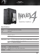
Redefine tradition Specifications Model SST-RV04B-W (black + window) Material Reinforced plastic outer shell, steel body Color Matte black Motherboard SSI-EEB, SSI-CEB, Extended ATX, ATX, Micro-ATX Drive Bay Exposed 5.25" x 2 Internal 3.5" x 7 (2 hot-swap) 2.5” x 4 Cooling System Front 2 x Air Penetrator AP181 180mm intake fan 600/900/1200rpm, 18/25/34dBA Backwards compatible with 3 x 120mm fans Rear 1 x 120mm fan slot (option) 8 Expansion Slot Front I/O Port USB 3.
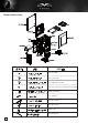
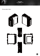
Disassemble Chart Secure 2.5” HDD Secure optical drives Secure VGA holder and claw Secure PSU, 12025 fan, motherboard and 3.
Disassemble Chart TOP LEFT SIDE RIGHT SIDE FRONT 4
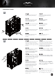
lnstallation Guide 1 Loosen two screws from both left and right side panels to remove them. Отвинтите по два винта, крепящих левую и правую боковых панели, и снимите панели. Lösen Sie die beiden Schrauben an den linken und rechten Seitenwänden, nehmen Sie die Seitenwände ab. 取下左右側板各兩顆螺絲,卸下側板。 Desserrez les vis des deux panneaux latéraux pour les retirer. 取下左右侧板各两颗螺丝,卸下侧板。 Desatornille dos tornillos de los paneles izquierdo y derecho para quitarlos.
lnstallation Guide 3 4 Loosen three screws holding the motherboard tray to remove it. Отвинтите три винта, крепящих кронштейн материнской платы, и снимите его. Lösen Sie die drei Schrauben, welche die Motherboard- Halterung fixieren, nehmen Sie die Halterung ab. 取下主機板托盤3顆螺絲, 將主機板托盤抽出。 Desserrez les trois vis tenant le plateau de la carte mère pour le démonter. 取下主机板托盘3颗螺丝, 将主机板托盘抽出。 Desatornille tres tornillos que sujetan la bandeja de la placa base para quitarla.
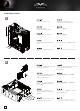
lnstallation Guide 5 Remove 3.5” drive cage. Извлеките кронштейн для 3,5-дюймовых жестких дисков. Nehmen Sie die 3,5 Zoll-Laufwerkhalterung heraus. 移除3.5”主硬碟架。 Retirez le casier des lecteurs 3.5”. 移除3.5”主硬盘架。 Quite la carcasa para dispositivos de 3,5” 3.5インチドライブケージを取り外します。 Rimuovere il supporto hard drive da 3,5” 3.5” 드라이브 케이지를 제거합니다. Loosen the screws holding the lower drive cage to remove it. Отверните винты крепления нижнего отсека для жестких дисков и извлеките его.
lnstallation Guide 7 Install 2.5” drive into the bottom of the chassis and secure with screws. Установите 2,5-дюймовый жесткий диск в нижнюю часть корпуса и закрепите его винтами. Installieren Sie das 2,5 Zoll-Laufwerk im unteren Teil des Gehäuses; anschließend mit Schrauben fixieren. 將2.5”硬碟裝入機殼底部,並鎖上螺絲。 Installez le lecteur 2.5” dans le bas du boîtier et fixez-le avec des vis. 将2.5”硬盘装入机壳底部,并锁上螺丝。 Instale el disco de 2,5” en la parte inferior de la carcasa y fíjelo con tornillos. ケース底部に2.
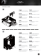
lnstallation Guide 9 10 Install motherboard rear I/O plate into the chassis. Установите в корпус заднюю панель ввода-вывода материнской платы. Installieren Sie das hintere I/O-Blech im Gehäuse. 將I/O彈片裝上機殼。 Réinstallez la cage de lecteur inférieur. Si vous voulez utiliser le CP05, vous pouvez l'installer maintenant. 将I/O弹片装上机壳。 Instale la placa trasera de E/S de la placa base en la carcasa. ケース内にマザーボード後部I/Oプ レートをインストールします。 Installare la placca I/O della scheda madre nella sede preposta.
lnstallation Guide 11 Setzen Sie die Motherboard-Halterung nebst Motherboard wieder in das Gehäuse ein. Sofern Sie das 4-polige ATX12V- oder das 8-polige EPS-Kabel bereits angeschlossen haben, achten Sie darauf, dass das Kabel durch die Öffnung zwischen Netzteil und Motherboard verläuft. Remettez la carte mère assemblé à son support dans le boîtier.
lnstallation Guide 13 Route all power supply cables to the opening on the left of the power supply. Проложите все кабели питания через отверстие слева от блока питания. Verlegen Sie sämtliche Netzteilkabel durch die Öffnung links vom Netzteil. 請將所有電源線穿過電源左邊的開孔。 Faîtes passer tous les câbles de l'alimentation par l'ouverture situé à sa gauche. 请将所有电源线穿过电源左边的开孔。 Enrute todos los cables de la fuente de alimentación por la abertura a la izquierda de la fuente de alimentación.
lnstallation Guide 15 Install hard drive cage back into the case with cables routed. Установите кронштейн для жестких дисков на место в корпус с проложенными кабелями. Bauen Sie die Laufwerkhalterung wieder das Gehäuse ein. Achten Sie darauf, die Kabel sauber zu verlegen. 將3.5”主硬碟架裝回機殼, 同時請注意理線。 Remettez le casier dans le boîtier avec faisant cheminer correctement les câbles. 将3.5”主硬盘架装回机壳, 同时请注意理线。 Instale de nuevo la carcasa para discos duros en la carcasa con los cables enrutados.
lnstallation Guide 17 Connect all cables for 5.25”, 3.5”, and 2.5” drives as needed. Подсоедините все кабели 5,25-дюймовых, 3,5-дюймовых и 2,5-дюймовых устройств соответствующим образом. Schließen Sie sämtliche Kabel für verwendete 5,25-, 3,5- und 2,5-Zoll-Laufwerke an. 先連接上所有磁碟需要用到的線材 (包含5.25”、3.5”以及 2.5”) Branchez tous les câbles pour les lecteurs 5.25”, 3.5”, et 2.5” selon vos besoins 先连接上所有磁盘需要用到的线材 (包含5.25”、3.5”以及 2.
lnstallation Guide 19 Insert 3.5” hard drive into the lower hard drive cage Установите 3,5-дюймовый жесткий диск в нижний отсек для жестких дисков Setzen Sie eine 3,5-Zoll-Festplatte in den unteren Festplattenkäfig ein 額外的3.5”硬碟,請安裝於底部硬碟架。 Insérez le lecteur 3,5" dans la cage du lecteur inférieur 额外的3.5”硬盘,请安装于底部硬盘架。 Inserte el disco duro de 3,5” en la carcasa inferior para discos duros. 一生懸命に3.5を挿入して」下部のハード ディスク・ケージに運転します Inserire il disco rigido 3.5” nel cage unità inferiore. 3.
lnstallation Guide 21 Reinstall both left and right side panel to complete installation. Installieren Sie zum Abschluss der Installation die linke und rechte Seitenwand wieder. Réinstallez les deux panneaux latéraux pour terminer le montage. Reinstale los paneles laterals izquierdo y derecho para completar la instalación. Reinstallare entrambi i pannelli laterali per completare l’installazione. Для завершения установки установите на место левую и правую боковые панели.
Connector definition (1) Front panel connector installation Power switch and reset switch installation guide: Please refer to the motherboard manuals for the motherboard’s “Front Panel Connector” or “System Panel Connector” pin definition. Power switch and reset switch have no polarity, so they can be connected in any orientation. Bitte suchen Sie in der Motherboard-Dokumentation nach der Pinbelegung der Anschlüsse des Frontbedienfeldes („Front Panel Connectors“ oder „ System Panel Connectors“).
Connector definition LED connector installation guide: Please refer to the motherboard manuals for the motherboard’s “Front Panel Connector ” or “System Panel Connector” pin definition.; the white/black wires are negative while other colors are positive wires. The Power LED wires are separate pins for compatibility with different motherboard pin definition so please make sure they are connected in the right polarity by referring to your motherboard manual.
Front I/O connector guide Below are the front I/O connectors pin definition, please also check your motherboard manual to cross reference with motherboard’s front I/O pin headers. SilverStone’s I/O connectors are in block type to simplify installation. Nachstehend finden Sie die Pinbelegung der vorderen E/A-Anschlüsse; bitte gleichen Sie zudem das Handbuch Ihres Motherboards mit den vorderen E/A-Pinzuweisungen ab. SilverStones E/A-Anschlüsse befinden sich zur Vereinfachung der Installation in Blockart.
Component size limitations The RV04 can accommodate all standard size components and even some that are out of spec, please refer to the following guidelines for component selection and future upgrade considerations: (1) CPU Cooler limitation The height limit is 165mm and there is 13mm of clearance around the motherboard’s top edge. The clearance toward the front of the case is variable depending on how much you fill the hard drive cage.
Component size limitations (2) Power supply and optical drive limitation (A) A: Length limitation The Total length for power supply and optical drive: Power supply and the optical drive space in the RV04 share the same plane so the total limit is 439mm including possible room for cables. We recommend maximum size for power supply of up to 220mm such as the SilverStone’s ST1500. Maximum length limitation for PSU only is 285mm. ( (A) The absolute maximum length for optical drive is 225mm.
A. Ограничение на длину Общая длина блока питания и приводов оптических дисков: Блок питания и привод оптических дисков в корпусе RV04 расположены на одной панели, поэтому их общая длина не может превышать 439 мм, включая возможное пространство для кабелей. Рекомендуется использовать блок питания длиной не более 220 мм, например модель SilverStone ST1500. Ограничение по длине для блока питания составляет 285 мм. ( (A) Максимально допустимая длина привода оптических дисков составляет 225 мм.
La RV04 puede aceptar tarjetas gráficas de hasta 13,3” (338mm). RV04 può supportare schede grafiche con una lunghezza massima di 13,3” (338mm). RV04 поддерживает графические карты потребительского уровня размером 13,3 дюйма (338 мм) RV04支援到PCIE規格定義的上限長度為13.3”帶把手的顯示卡。 如果您還是有安裝不下的顯示卡,請與我們聯繫,並告知我們顯示卡的廠牌與型號,由我們協助您後續安裝事宜。 RV04支持到PCIE规格定义的上限长度为13.3”带把手的显示卡。 如果您还是有安装不下的显示卡,请与我们联系,并告知我们显示卡的厂牌与型号,由我们协助您后续安装事宜。 RV04は13.3インチ(338mm)の市販グラフィックカードをサポートできます。 RV04은 최대 13.3”(338mm)의 그래픽 카드를 지원합니다.
Component size limitations (5) Motherboard size limitation RV04 supports up to SSI-EEB (Extended ATX motherboard), New generation of SSI-CEB server or workstation motherboards no longer require CPU cooler mounting holes on the motherboard tray. Coolers can now be installed directly on the motherboard.
RV04最大支援至SSI-EEB(俗稱E-ATX)規格主機板 圖: 新一代SSI-CEB規格伺服器主機板,已經沒有依照SSI規範的Xeon Cooler在機殼上的鎖固孔位, 其Cooler本身是鎖在主機板上。我們新一代的機殼為了配合LGA1156/1155的位置,將主機板底板對應的開孔加大,因而取消了SSI規範上的Cooler 鎖固螺柱。並不是不相容於SSI CEB主機板,只是因應主機板規格的演進而修改設計。 須請您注意的事是,許多伺服器主機板可能會有多增加一些非標準的鎖固孔位。 RV04只會有規範上應該有的鎖固孔位。 RV04最大支持至SSI-EEB(俗称E-ATX)规格主机板 新一代SSI-CEB规格服务器主机板,已经没有依照SSI规范的Xeon Cooler在机壳上的锁固孔位, 其Cooler本身是锁在主机板上。我们新一代的机壳为了配合LGA1156/1155的位置,将主机板底板对应的开孔加大,因而取消了SSI规范上的Cooler 锁固螺柱。并不是不兼容于SSI CEB主机板,只是因应主机板规格的演进而修改设计。 须请您注意的事是,许多服务器主机板可能会有多增加一些非标准的锁固孔位。 RV04只会有规范
A : CPU Cooler Supporter (1) Premièrement mettez le boîtier sur le côté, vérifiez bien qu'il soit bien à plat (2) Le support intégré du processeur a déjà été installé dans une position couramment utilisé. Vous pouvez desserrer la vis du milieu pour l'étendre complètement (3) Si la position du support n'est pas optimale pour votre configuration, retirez deux vis supplémentaires sur les côtés gauche et droit pour bougez le support.
A : CPU Cooler Supporter (1) 请先翻倒机壳,维持机壳平躺。 (2) CPU Cooler支撑架已经预先安装在适当的位置,请先松开前面的螺丝,把支撑架展开。 (3) 如果支撑架的位置不适当,请再移除中间螺丝;将支撑架前后移动至适当位置再锁固。 (4) 将支撑架展开至刚好接触到CPU Cooler本体部分的下边缘,然后锁固中间的螺丝。 (5) 直立起机壳,Cooler会自然的躺在支架上。 (6) 支撑架的适用范围:板外13mm至板内45mm 请斟酌使用。我们建议您使用在120mm以上风扇规格的塔型Cooler B:VGA Supporter (1) 请先翻倒机壳,维持机壳平躺。 (2) 将显示卡支撑架锁上机壳,可前后调整至不挡住显卡电源插头的位置。 (3) 视显示卡槽位而定,锁上支撑架的挂钩。注意,如果有多卡安装时,不要让显示卡相邻安装,挂勾无法伸入两张卡之间的缝隙。 A : CPU Cooler Supporter (1) まず、側面を下にしてケースを置き、水平面にあるのを確かめます (2) CPUサポーターは一般的に使われる位置にインストール済みです。完全にそれを拡張するには、中
Optimal Thermal Performance Layout (2) When choosing a graphics card, we recommend models that have fan blowing exhaust air to the rear slot, this will ensure smooth and efficient airflow within the RV04 for maximum cooling performance. Bei der Auswahl von Grafikkarten empfehlen wir Modelle, die warme Luft über eine Öffnung im hinteren Teil des Steckplatzes in die Außenwelt ableiten; dies gewährleistet eine ungestörte und wirksame Luftzirkulation innerhalb des RV04 und sorgt für eine optimale Kühlung.
Fare riferimento alle figure che seguono A. Vi sono numerosi punti, dietro al supporto scheda madre, che possono erre utilizzati per l’organizzazione dei cavi. Обращайтесь к следующим чертежам A.За лотком системной платы имеется множество проушин для безопасного крепления кабелей. 你可以參考下面兩張圖範例做整線規畫 特別說明: A. 背面有大量的理線凸橋,可以斟酌把線材固定其上。 你可以参考下面两张图范例做整线规画 特别说明: A. 背面有大量的理线凸桥,可以斟酌把线材固定其上。 以下の図を参照してください A. マザーボードトレイ背面には、ケーブル取り回しに利用できる多くのケーブルタイバンドブリッジがあります。 다음 다이어그램을 참조하십시오 A.
B. 上图表示主机板托盘开孔的用途,请您参考使用。 C. 主机板前折边与左侧板,光驱架上缘与上盖的间隙都不足10mm。请不要让线材穿过这些地方,避免损坏。这些都是结构补强所必要的机构,请见谅。 B. 図には開口部が、どのケーブルのために設計されているかが示されています。 C. マザーボードトレイのフロント縁と左側パネルの間には10mm未満の間隙があります。5.25インチドライブトレイ上部と上部カバーの間の間隙も10mm未満です。 これらは構造強化エリアの一部として設計されており、ケーブルやコネクタ類を保存する目的はありません。それで損傷防止のため、ケーブル取り回しにこれらの小さな間隙 を使わないでください。 B. 그림에는 개구부가 어떠한 케이블을 위해 설계되었는지 나와 있습니다. C. 메인보드 트레이 전면 가장자리와 왼쪽 사이드 패널 사이의 간격은 10mm 정도 있습니다. 5.25” 드라이브 트레이와 상부 커버의 간격도 약 10mm 정도 있습니다.
RV04的180mm穿甲彈風扇可以允許轉速調整為600/900/1200rpm 180風扇開關說明圖:"L"代表風扇處於低轉速的工作狀態,正中間為中轉速,"H"代表風扇處於高轉速的工作狀態。 RV04的180mm穿甲弹风扇可以允许转速调整为600/900/1200rpm 180风扇开关说明图:"L"代表风扇处于低转速的工作状态,正中间为中转速,"H"代表风扇处于高转速的工作状态。 RV04の空の侵入者ファンは、600rpm、900rpmまたは1200rpmの間で可調速度です。速度は、無言であるかパフォーマンス使用のために設計されます。 180mmは、スイッチ・ガイドに風を送ります:「L」、と、低速州(中程度の速度州のための中央の位置)は示します。「H」は、高速州を示します。 RV04의 Air Penetrator 팬은 600rpm, 900rpm 또는 1200rpm으로 속도를 조정할 수 있습니다. 저소음 또는 성능 용도에 맞출 수 있도록 여러 속도가 설계된 것입니다.
La conception à pression d'air positive du RV04 est une configuration efficace permettant de réduire l'accumulation de la poussière dans le boîtier. De petites particules d'air ou de peluche vont s'accumuler avec le temps sur les filtres d'aspiration, et non sur les composants à l'intérieur du boîtier.
Beim RV04 werden feinere Luftfilter eingesetzt, die einen höheren Luftdurchsatz ermöglichen. Diese weisen ein identisches Filtervermögen auf, jedoch mit einem im Vergleich zu älteren Nylon-Filtern um 65 – 90 % gesteigerten Luftdurchsatz. Allerdings sind diese feineren Filter etwas weniger robust; beachten Sie daher die folgenden Vorsichtsmaßnahmen bei der Reinigung. Reinigungsmethoden: 1. Reinigung mit einer weichen Bürste Der Lüfterfilter kann mit einer weichen Bürste gereinigt werden.
В корпусе SG09 применяются мелкопористые фильтры с увеличенным пропускной способностью воздушного потока. При одинаковой эффективности фильтрации их пропускная способность по сравнению с нейлоновыми фильтрами предыдущего поколения увеличилась с 65% до 90%. Однако новые фильтры менее прочные, поэтому при их чистке следует соблюдать следующие меры предосторожности. Способы чистки 1. Чистка мягкой щеткой Фильтр допускается чистить щеткой с мягкой щетиной.
RV04는 공기 흐름 비가 매우 높은 미세한 공기 필터를 사용합니다. 이 필터는 이전 세대의 나일론 필터와 비교할 때 여과 성능은 동일하지만 공기 흐름 비는 65%에서 90%로 증가했습니다. 그러나 미세한 필터는 내구성이 그만큼 좋지 않기 때문에 필터 청소 시 다음과 같은 주의사항에 유의하십시오. 청소 방법: 1. 부드러운 솔을 사용한 청소 팬 필터는 부드러운 솔을 사용하여 청소할 수 있습니다. 필터를 손상시키는 철로 된 솔은 사용하지 마십시오. 팬 필터를 청소할 때는 불필요한 먼지를 들이마시지 않도록 마스크를 착용하는 게 좋습니다. 2. 진공 청소기를 사용한 청소 팬 필터를 분리하는 게 어려운 경우, 진공 청소기를 사용하여 청소하는 게 가장 좋은 방법입니다. 진공 청소기가 팬 블레이드를 손상시키지 않도록 하려면, 청소하기 전에 이를 고정하십시오. 3. 물을 사용한 청소 물로 헹구는 것이 팬 필터를 가장 깨끗하게 청소하는 방법입니다.
La CP05 y CP05-SAS se pueden comprar por separado si desea tener función de cambio en caliente. Por favor, tenga en cuenta lo siguiente: A. Si necesita cambiar sus discos duros mientras se ejecuta un sistema operativo (cambio en caliente), necesita asegurarse de que el chipset SATA (ó southbridge de la placa base) usado para conectar los discos duros tiene los controladores y funcionalidad adecuados.
A. Retirez les deux panneaux latéraux B. Ouvrez la porte d’accès frontal et enlevez le filtre du ventilateur. C. Desserrez les vis fixant le ventilateur pour le démonter D. Dévissez les vis qui tiennent le commutateur de vitesse du ventilateur, puis placez le commutateur à travers le trou du panneau frontal. (Note : Veuillez utiliser un petit tournevis pour ceci) E. Pour réinstaller le ventilateur, veuillez simplement suivre les instructions en sens inverse. A. Quite los paneles izquierdo y derecho B.
1. Fixez le ventilateur en utilisant une vis de ventilateur normale sur la console de transfert inclus dans la boîte d’accessoires de RV04. 2. Utilisez la vis courte (#6-32) pour visser la console sur la masse. 1. Fije el ventilador usando tornillos para ventilador normales en el bracket de transferencia que está incluido en la caja de accesorios de la RV04. 2. Use el tornillo corto (#6-32) para atornillar el bracket al chasis. 1.
Kensington Security Slot Un câble de verrouillage peut être acheté pour utilisé l'emplacement de sécurité Kensington situé à l'arrière du RV04 pour empêcher le boîtier d'être déplacé ou ouvert. Prudence : Veuillez vérifier la compatibilité avant d'acheter le verrou et le câble pour l'utiliser avec l'emplacement de sécurité Kensington du RV04.
Q: Why isn’t an exhaust fan included? A: The RV04’s airflow path has been optimized using positive pressure design to dissipate heat. The two front 180mm fan will provide equal airflow for both CPU and graphic card area. From our test results, a rear exhaust fan creates an imbalanced airflow that lowers the CPU temperature slightly at the cost of greater cooling performance loss for the graphics card area. Even without an exhaust fan installed the hot air will still exit naturally from the rear.
Q: I have an entry level liquid cooling system, where should I install the radiator? A: A.
Q: When I turn on the computer, why doesn’t the front 180mm spin? A: A. If your fan is connected to the motherboard, we suggest you to turn off temperature control function in the BIOS. If you want to use temperature control function on your motherboard, we recommend you to set the RV04’s physical fan speed switch to high for a lower starting voltage and a wider range of control. If the fans still do not spin, please contact reseller or SilverStone to arrange for replacement. F.
Q: 理由は、私がトップカバーを取り外すためにサイドパネルを取り外さなければならないことをします? A: このシャシー支持物ケンジントン保安が全てのシャシーだけがロックしたが、内部の構成要素の窃盗を防止することもできるとき、とられるのを防がないためにロックするA.。 トップカバーが独立して取り外されることができるならば、第一にケンジントン・ロック穴を持っても無駄である。 Q. 상단 커버를 분리하려면 측면 패널을 분리해야 하는데, 이유가 무엇입니까? A. 이 섀시는 잠가졌을 경우 섀시 전체뿐만 아니라 내부의 구성품도 도난되지 않도록 보호하는 켄싱턴 보안 잠금을 지원합니다. 상단 커버를 독립적으로 분리할 수 있다면, 첫째로 켄싱턴 잠금 구멍을 만들 수 있는 데가 없게 됩니다. Q: I want to install customized liquid cooling system, do you have any recommendation? A: A.
Warranty Information This product has a limited 1 year warranty in North America, and Australia. For information on warranty periods in other regions, please contact your reseller or SilverStone authorized distributor. Warranty terms & conditions 1. Product component defects or damages resulted from defective production is covered under warranty. Defects or damages with the following conditions will be fixed or replaced under SilverStone Technology’s jurisdiction.
January, 2013 G11218040