LITE SG06 The golden standard of Mini-ITX cases
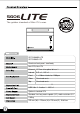
LITE SG06 The golden standard of Mini-ITX cases SST-SG06BB-LITE SST-SG06S-LITE Aluminum front panel, steel body Mini-DTX, Mini-ITX External 12.7mm slim optical drive x 1 Internal 3.5” x 1 , 2.5” x 1 Front 1 x 120mm intake fan 1200rpm Sides Oversized vents Top Oversized vents 2 USB 3.0 x 2、Audio x 1、MIC x 1 Optional standard SFX Standard size long cards capable (10”), width restriction-5.11" 2.43kg 222 mm (W) x 176 mm (H) x 276 mm (D), 10.
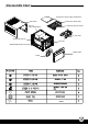
SLIM OPTICAL DRIVE (SOLD SEPARATELY) SLIM OPTICAL DRIVE TRAY TOP COVER SFX PSU (SOLD SEPARATELY) 2.5” HDD BAY (NOT INCLUDED) 3.
3 Please remove the screws holding the top cover with a screw driver, then pull it toward the back to lift it outward away from the chassis. С помощью отвертки открутите шурупы, удерживающие верхнюю крышку, а затем снимите ее, сдвинув назад и приподняв. Bitte entfernen Sie die Schrauben der oberen Abdeckung mit einem Schraubenzieher und ziehen Sie die Abdeckung nach hinten, weg von dem Chassis.
Remove the screws holding the hard drive bracket with a screw driver as shown, then remove the cage outward from the chassis. С помощью отвертки открутите шурупы, удерживающие кронштейн жесткого диска, как показано на рисунке, и выньте из корпуса корзину жесткого диска. Entfernen Sie die Schrauben der Festplattenhalterung mithilfe eines Schraubenziehers wie abgebildet und nehmen Sie die Halterung aus dem Chassis.
5. Press the area as shown to release the clips, then remove the front panel. Нажмите на указанные зажимы и снимите переднюю панель. Drücken Sie auf die Stelle wie abgebildet, um die Klemmen zu lösen und entfernen Sie die Frontabdeckung. 請依圖示輕按卡榫以卸下前面板。 Appuyez sur la zone comme montré pour détacher les clips, puis retirez le panneau frontal. 请依图示轻按卡榫以卸下前面板。 Presione la zona como se muestra para soltar los enganches, luego quite el panel frontal.
7. Tab Remove the tab of optical drive bay with a screw driver. С помощью отвертки уберите накладку отсека для оптического привода. Entfernen Sie Klappe des optischen Laufwerkschachtes mithilfe eines Schraubenziehers. 請以螺絲起子折斷光碟機槽上的檔片。 Retirez l’attache de la baie du lecteur optique avec un tournevis. 请以螺丝起子折断光驱槽上的文件片。。 Quite la presilla de la bahía del dispositivo óptico con un destornillador. 光学ドライブベイのタブをドライバーで取り外します。 Rimuovere la mascherina del bay del lettore ottico con un cacciavite.
. Install your motherboard into the chassis as shown and secure with included screws. Установите материнскую плату в корпус и закрепите ее прилагаемыми шурупами. Installieren Sie Ihr Motherboard im Chassis und befestigen Sie es mit den beiliegenden Schrauben. 將主機板裝入機殼內並以內附螺絲鎖固。 Retirez l’attache de la baie du lecteur optique avec un tournevis. 将主机板装入机壳内并以内附螺丝锁固。 Instale su placa base en el chasis como 図のようにマザーボードをケースにインス se muestra y asegúrela con los tornillos トールし、付属のネジで固定します。 incluidos.
11. Install your slim optical drive onto the bracket and secure with included screws. Установите тонкий оптический привод в кронштейн и закрепите прилагаемыми шурупами. Installieren Sie Ihr dünnes optisches Laufwerk in der Halterung und befestigen Sie es mit den beiliegenden Schrauben. 將薄型光碟機裝入光碟機架並以內附螺絲鎖固。 Installez votre lecteur optique slim sur le casier et fixez-le avec les vis incluses.
13. 14. 9 Reinstall the optical drive bracket into the chassis and secure with screws Установите кронштейн оптического привода в корпус и закрепите его шурупами . Installieren Sie die Halterung für optische Laufwerke wieder im Chassis und befestigen Sie sie mit Schrauben 將光碟機架裝回機殼內並以步驟四卸下的 螺絲鎖固。 Réinstallez le casier du lecteur optique dans le boîtier et fixez-le avec des vis 将光驱架装回机壳内并以步骤四卸下的 螺丝锁固。 Reinstale el bracket para dispositivos ópticos en el chasis y asegúrelo con tornillos .
15. 16. Please remove the screws holding the expansion card slot cover, and remove it. Открутите шурупы на крышке слота карты расширения и снимите крышку. Bitte entfernen Sie die Schrauben der Expansionssteckplatzabdeckungen und entfernen Sie sie. 請將鎖固擴充槽檔片的螺絲卸下,再將 擴充槽檔片卸下。 Veuillez retirer les vis fixant les équerres des emplacements d’extension, puis retirez-les selon vos besoins.
17. Reinstall the expansion card slot cover and secure with screws. Поместите на место крышку слота карты расширения и закрепите ее шурупами. Installieren Sie die Expansionssteckplatzabdeckung wieder und befestigen Sie sie mit Schrauben. 裝回擴充槽檔片並以螺絲鎖固。 Réinstallez la fixation des équerres et fixez-le avec des vis. 装回扩充槽档片并以螺丝锁固。 Reinstale la cubierta del zócalo de la tarjeta de expansión y fíjela con tornillos. 拡張カードスロットカバーを戻し、 ネジで固定します。 Reinstallare la mascherina e serrarlo per mezzo delle viti.
19. Attach the rubber standoff onto the chassis appropriately as required. Прикрепите к корпусу резиновые опоры. Befestigen Sie den Gummi-Abstandhalter am Chassis wie benötigt 依需求將橡膠腳墊適當地貼附於機殼上。 Collez les pieds en caoutchouc convenablement sous le boîtier comme exigé. 依需求将橡胶脚垫适当地贴附于机壳上。 Enganche la base de goma en el chasis si es necesario. 必要に応じてケースにゴム製スタンドを取り 付けます。 Applicare i piedini in gomma sul telaio. 고무 받침을 필요한만큼 케이스에 부착합니다. 20. Installation complete. Установка завершена.
Connector definition (1) Front panel connector installation Power switch and reset switch installation guide: Please refer to the motherboard manuals for the motherboard’s “Front Panel Connector” or “System Panel Connector” pin definition. Power switch and reset switch have no polarity, so they can be connected in any orientation. Bitte suchen Sie in der Motherboard-Dokumentation nach der Pinbelegung der Anschlüsse des Frontbedienfeldes („Front Panel Connectors“ oder „ System Panel Connectors“).
Connector definition LED connector installation guide: Please refer to the motherboard manuals for the motherboard’s “Front Panel Connector ” or “System Panel Connector” pin definition.; the white/black wires are negative while other colors are positive wires. The Power LED wires are separate pins for compatibility with different motherboard pin definition so please make sure they are connected in the right polarity by referring to your motherboard manual.
Front I/O connector guide Below are the front I/O connectors pin definition, please also check your motherboard manual to cross reference with motherboar front I/O pin headers. SilverStone’s I/O connectors are in block type to simplify installation. Nachstehend finden Sie die Pinbelegung der vorderen E/A-Anschlüsse; bitte gleichen Sie zudem das Handbuch Ihres Motherboards mi den vorderen E/A-Pinzuweisungen ab. SilverStones E/A-Anschlüsse befinden sich zur Vereinfachung der Installation in Blockart.
Component size limitations Although the SG06-Lite is small, it is still compatible with many oversized components, please refer to the following guidelines for component selection and future upgrade considerations: (1) CPU cooler height limitation 12025FAN The SG06-Lite has 82mm height limitation for CPU cooler.
Component size limitations (2) PSU limitation The SG06-Lite supports standard SFX power supply with a 100mm depth. Der SG06-Lite unterstützt SFX-Standardnetzteile mit einer Tiefe von 100 mm. Le SG06-Lite supporte une source d'alimentation SFX standard avec une profondeur de 100mm. La SG06-Lite acepta fuentes de alimentación SFX estándar con una profundidad de 100mm. SG06-Lite supporta l’alimentatore standard SFX con una profondità di 100 mm.
Component size limitations (3) Graphics card/expansion card length limitation SG06-Lite can support 10”(254mm) consumer level graphics cards Graphic card length reference: NVIDIA GeForce GTX 660/660Ti/670 – 9.5” AMD Radeon HD7870- 9.75” NVIDIA GeForce GTX 680 - 10" Das SG06-Lite nimmt bis zu 254 mm lange Grafikkarten auf. Graphic card length reference: NVIDIA GeForce GTX 660/660Ti/670 – 9.5” AMD Radeon HD7870- 9.
Component size limitations (4) Optical drive limitation SG06-Lite accommodates only 12.7mm thick slim optical drive Below are examples of 12.7mm thick optical drives. Das SG06-Lite nimmt ausschließlich 12,7 mm dünne optische Slim-Laufwerke auf. Nachstehend finden Sie Beispiele zu optischen 12,7 mm-Laufwerken. SG06-Lite loge seulement un disque optique mince de 12,7 mm d'épaisseur. Nous vous présentons quelques exemples de disques optiques de 12,7 mm d'épaisseur ci-dessous.
Upgrade and Maintenance (1) Fan filter removal guide An example of a GPU cooler that is filled with dust and has lost most of its cooling performance SG06-Lite’s positive air pressure design is an effective configuration that will reduce dust buildup inside the case. Small air particles or lint will accumulate over time on intake filters instead of on the components inside the case.
Upgrade and Maintenance A. Please remove the screws holding the top cover with a screw driver, then pull it toward the back to lift it outward away from the chassis. С помощью отвертки открутите шурупы, удерживающие верхнюю крышку, а затем снимите ее, сдвинув назад и приподняв.
Upgrade and Maintenance C. Remove the fan filter Снимите фильтр вентилятора. Entfernen Sie den Lüfterfilter. 將濾網取下 Enlever le filtre du ventilateur. 将滤网取下 Retire el filtro del ventilador. ファンフィルタの取り外し Rimuovere il filtro della ventola 팬 필터 분리 Loosen the 4 screws to remove the fan from the inside of the case. Undo the above steps to install the top cover. Чтобы извлечь вентилятор из корпуса, отверните 4 винта. Для установки верхней крышки повторите описанные выше операции в обратном порядке. D.
Warranty Information This product has a limited 1 year warranty in North America and Australia. For information on warranty periods in other regions, please contact your reseller or SilverStone authorized distributor. Warranty terms & conditions 1. Product component defects or damages resulted from defective production is covered under warranty. Defects or damages with the following conditions will be fixed or replaced under SilverStone Technology’s jurisdiction.
February G11218750