SG08-LITE
The ultimate evolution of high performance Mini-ITX SG08-LITE For years, SilverStone Sugo series has been the benchmark and the standard for high-performance Mini-ITX chassis. The SG08-LITE was designed to retain all the signature features from the award-winning SG08 such as the compact 14.8-liter design that can accommodate graphic card up to 12.2” and the premium 10mm aluminum front panel where SilverStone engineers have further updated the slim optical slot into slot-loading variety for cleaner styling.
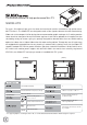
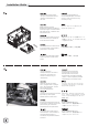
Disassemble chart HDD CAGE 3.5” HDD X 1 TOP COVER EXPANSION SLOT X 2 2.5”HDD X 2 FAN BRACKET SLIM SLOT - LOADING OPTICAL DRIVE (OPTION) USB 3.0 + SPK + MIC MINI - ITX (OPTION) POWER BUTTON POWER LED & HDD LED ATX PSU (OPTION) FAN FILTER PSU FILTER PICTURE ITEM PURPOSE SCREW A M2 X 2 Secure optical drive SCREW B M3 X 4 Secure 2.5" SSD/HDD SCREW C 632 X 6 Secure motherboard SCREW D 632 X 10 Secure 3.
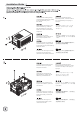
Installation Guide Unscrew screws holding the top cover and then remove it by pulling to the rear and away from the chassis. Выкрутите крепежные винты верхней крышки, а затем снимите ее, потянувназад и в сторону от корпуса. Lösen Sie die Schrauben an der oberen Abdeckung; entfernen Sie die Abdeckung, indem Sie diese nach hinten vom Gehäuse wegziehen 상부커버를 고정하고 있는 나사를 제거한후, 뒤쪽으로 당겨 커버를 제거합니다. Dévisser les vis arrière maintenant le capot supérieur et tirer le capot supérieur vers l’arrière.
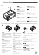
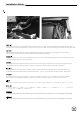
Installation Guide ① Unscrew screws holding the hard drive bracket to remove it. ② Loosen the screw on the PSU cage to remove it. ③ Secure the PSU onto the PSU cage. ④ Secure the PSU cage onto the chassis with screws. Connect the power cord. Unscrew screws holding the optical drive bracket to remove it. Выкрутите крепежные винты кронштейна привода оптических дисков, чтобы извлечь его. Entfernen Sie die Abdeckung des optischen Laufwerks, indem Sie die in der Abbildung gezeigten Schrauben lösen.
Installation Guide Insert the I/O shield included with your motherboard and then install the motherboard into the case. Установите экранированную панель ввода/вывода системной платы, а затем установите саму системную плату. Setzen Sie das mit Ihrem Motherboard gelieferte I/O-Blech in die Aussparungen an der Rückseite des Gehäuses ein, installieren Sie anschließend das 메인보드 후면 I/O 커버를 설치한 후 메인보드를 설치합니다. Insérez la plaque d'E/S inclus avec votre carte mère, puis installez la carte mère dans le boîtier.
Installation Guide We recommend at this point to start thinking about routing the cables cleanly by fastening ATX 24pin and EPS 8pin/ATX 4pin cables on a bridge next to the power supply bracket. You may need to store excess cables in the area located on the left side of the hard drive cage. Wir empfehlen, an dieser Stelle eine saubere Kabelführung zu beachten, indem Sie die 24-poligen ATX- und 8-poligen EPS-/4-poligen ATX-Kabel an einer Brücke neben der Netzteilhalterung befestigen.
Installation Guide We recommend to route the USB and audio front I/O cables around the front of hard drive cage, there should be sufficient bridges for fastening the cables. Wir empfehlen die Führung der USB- und E/A-Audiofrontkabel um die Vorderseite des Festplattenkäfigs; es sollten genügend Brücken zur Befestigung der Kabel vorhanden sein La longueur de câble superflu peutêtre dissimulée sur le côté droit de la cage disque dur.
Installation Guide Excess front panel connector cables can be fastened on the bottom panel of the case. Излишки кабелей к разъемам передней панели можно закрепить на нижней панели корзины. Die restlichen FrontblendenAnschlusskabel können an der unteren Blende des Gehäuses befestigt werden. 불필요하거나 남는 패널커넥터와 케이블은 케이스 하부 패널에 고정하면 됩니다. L’excès de câble des prises additionnelles peut-être dissimulé dans le bas du boitier.
Installation Guide Install and secure the hard drive cage with screws. Установите и закрепите корзину жестких дисков винтами Installieren und befestigen Sie den Festplattenkäfig mit Schrauben. 하드 드라이브 케이지를 설치한 후 나사로 고정합니다. Réinstallez le casier à disques durs dans le boîtier comme montré. ハードドライブケージを取り付け、 ネジで固定します。 Instale y fije la carcasa para discos duros con tornillos. 將硬碟架安裝上機殼,並鎖上螺絲 Installare ed assicurare la gabbia degli hard disk al case.
Installation Guide We recommend connecting all fan or SATA cables to the motherboard now as installation of graphics or expansion card may prevent installation of these cables. Wir empfehlen, nun alle Kühler- oder SATA-Kabel am Motherboard anzuschließen, da die Installation der Grafik- oder Erweiterungskarte die Verbindung dieser Kabel erschweren oder verhindern kann. Nous recommandons de brancher tous les câbles SATA et FAN avant d’installer les cartes filles ou cartes graphiques.
Installation Guide Remove expansion slot screws to remove expansion slot covers. Lösen Sie zum Entfernen der Abdeckung die Schrauben des Erweiterungssteckplatzes. Retirer les vis des slots d’extension pour retirer les caches. Quite los tornillos de las ranuras de expansión para retirar las cubiertas de las ranuras de expansión. Svitare le viti di serraggio dei cover degli slot di espansione per rimuovere i cover stessi. Выверните винты слотов расширения, чтобы снять заглушки слотов.
Installation Guide Install graphics or expansion card into the case then connect any required power cables to the card. Installieren Sie die Grafik- oder Erweiterungskarte im Gehäuse; schließen Sie dann alle erforderlichen Netzkabel an der Karte an. Installer les cartes graphiques ou cartes filles et relier les câbles nécessaires. Instale la tarjeta gráfica o de expansión en la carcasa y luego conecte cualquier cable de potencia necesario a dicha tarjeta.
Installation Guide Install slim optical drive onto the optical drive bracket and secure with included screws. IУстановите тонкий привод оптических дисков на специальный кронштейн и закрепите прилагающимися винтами. Installieren Sie ein schmales optisches Laufwerk an der Halterung des optischen Laufwerks; befestigen Sie dieses mit den mitgelieferten Schrauben. 슬림 광드라이브를 광드라이브 브라켓에 설치한후 나사로 고정합니다.
Installation Guide Place the top cover back onto the case and secure with screws. Platzieren Sie die obere Abdeckung wieder am Gehäuse und befestigen diese mit Schrauben. Remettre en place le capot supérieur du boitier et le fixer à l’aide de vis. Vuelva a poner la cubierta superior en la carcasa y fíjela con tornillos. Riposizionare il cover superiore sul case ed assicurarlo alla struttura con le viti. Установите верхнюю крышку обратно на корпус и закрепите винтами. 상부커버를 케이스에 재 설치한 후 나사로 고정시킵니다.
Connector definition (1) Front panel connector installation no polarity, so they can be connected in any orientation Power switch and reset switch installation guide: Please refer to the motherboard manuals for the motherboard’s “Front Panel Connector” or “System Panel Connector” pin definitio Power switch and reset switch have no polarity, so they can be connected in any orientation.
Connector definition LED indicators installation guide Please refer to the motherboard manuals for the motherboard’s “Front Panel Connector ” or “System Panel Connector” pin definition.; the white/black wires are negative while other colors are positive wires. The Power LED wires are separate pins for compatibility with different motherboard pin definition so please make sure they are connected in the right polarity by referring to your motherboard manual.
Front I/O connector guide Below are the front I/O connectors pin definition, please also check your motherboard manual to cross reference with motherboard’s front I/O pin headers. SilverStone’s I/O connectors are in block type to simplify installation. Nachstehend finden Sie die Pinbelegung der vorderen E/A-Anschlüsse; bitte gleichen Sie zudem das Handbuch Ihres Motherboards mit den vorderen E/A-Pinzuweisungen ab. SilverStones E/A-Anschlüsse befinden sich zur Vereinfachung der Installation in Blockart.
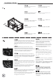
Component size limitations The SG08-LITE can accommodate all standard size components and even some that are out of spec, please refer to the following guidelines for component selection and future upgrade considerations. (1) CPU cooler height limitation CPU cooler height limitation 147mm (2) PSU limitation Depth limitation Power supply depth limitation 140mm The SG08-LITE supports power supply with depth of up to 160mm. To support graphics card longer than 7.
Component size limitations Accepte les blocs d'alimentation au standard ATX jusqu'à une longueur de 160mm. Pour accepter une longue carte graphique (de plus de 7,25”), la dimension du bloc d'alimentation ATX est limitée à 140mm, et uniquement aux blocs d'alimentation non modulaires. Les câbles doivent se trouver à droite du bloc d'alimentation. La SG08-LITE acepta fuentes de alimentación con una profundidad de hasta 160mm.
Component size limitations 위의 그림은 PSU 브래킷의 레이아웃입니다. 모든 구성부품이나 커넥터는 이 영역 안으로 들어와서는 안 됩니다(예: 스위치 또는 LED).
Component size limitations (3) Graphics card/expansion card length limitation Graphics card / expansion card length limitation SG08-LITE can support 12.2”consumer-level graphics cards (width 4.84”). Due to design, the graphics or expansion card when installed will be situated very close to the power supply so we recommend using cards with backside components no taller than 3.21mm. Most cards that follow standard reference designs should have no compatibility problems.
Component size limitations (4) Optical drive limitation The SG08-LITE only supports 12.7mm slim “slot-loading” optical drives. Below is an example of 12.7mm optical drive. Das SG08-LITE unterstützt nur schmale optische Laufwerke („Slot-In“). Nachstehend finden Sie Beispiele zu optische 12,7 mm-Laufwerke. Le SG08-LITE est compatible seulement avec le lecteur optique slim sans tiroir de 12,7mm (mange-disque aka “slot-loading”). Un exemple de lecteur optique de 12,7 mm est présenté.
Optimal Thermal Performance Layout Using SilverStone’s NT06-PRO without CPU fan is possible on CPU with TDP rated up to 95W. With a 120mm fan installed on the NT06-P, the use of a CPU with TDP rating of up to 130W is possible. We recommend using SATA connector with 90 degree angle for the 3.5” hard drive in order to use larger CPU cooler such as SilverStone’s NT06-P or bigger. Die Nutzung des NT06-PRO von SilverStone ohne CPU-Kühler ist bei CPUs mit einer TDP-Angabe von bis zu 95 W möglich.
Optimal Thermal Performance Layout Cable routing We placed pass-through holes on the back of the case, please use wire ties in places as needed by your hardware configuration. Hinter dem Motherboard-Einschub befinden sich Haken, die der Verwendung von Kabelbändern dienen. Il y a des crochets derrières le support de la carte mère pour utiliser des attaches pour regrouper les câbles. Hay ganchos detrás de la bandeja de la placa para poder usar bridas y así enrutar los cables. Por favor.
Maintenance and upgrade Fan and fan filter disassembly guide If you need to change fans, clean, or upgrade a fan, please refer to the following steps: (1) (2) (3) (4) 1. Unscrew screws holding the fan bracket and then pull up and away from the case. 2. Remove the 180mm fan filter as shown in the illustration. 3. Unscrew four screws holding the fan and two screws holding the graphics/expansion card security brace. When reinstalling both items, be sure to install them in the correct orientation. 4.
Maintenance and upgrade 1. Выкрутите крепежные винты кронштейна вентилятора, а затем потяните его вверх и в сторону от корпуса. 2. Снимите фильтр вентилятора размером 180 мм, как показано на рисунке. 3. Выкрутите четыре крепежных винта вентилятора и два крепежных винта предохранительного кронштейна графической карты/платы расширения. При установке обоих компонентов обратно на место соблюдайте правильную ориентацию. 4. Установите на место кронштейн 180-мм вентилятора и закрепите тремя винтами.
Maintenance and upgrade La conception à pression d'air positive du SG08-LITE est une configuration efficace permettant de réduire l'accumulation de la poussière dans le boîtier. De petites particules d'air ou de peluche vont s'accumuler avec le temps sur les filtres d'aspiration, et non sur les composants à l'intérieur du boîtier.
Maintenance and upgrade 1. After removing the top cover, the 180mm fan filter can slide out easily. 2. Flip the entire case upside-down, unscrew the screws holding the power supply filter to remove it. 1. Nach der Entfernung der oberen Gehäuseabdeckung können Sie den 180 mm-Lüfterfilter einfach herausziehen. 2. Drehen Sie das gesamte Gehäuse um; lösen Sie die Schrauben des Netzteilfilters und entfernen Sie ihn. 1.
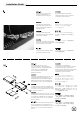
Recommended SilverStone products SST-SOB02 SOB02 is a slot-loading slim DVD burner with included SATA adapter and cable SST-NT06-PRO NT06-PRO offers high performance cooling with specific space requirements SST-SDP08 Use SDP08 to convert an available 3.5" drive bay into two 2.5" drive bays.
Warranty Information This product has a limited 1 year warranty in North America and Australia. For information on warranty periods in other regions, please contact your reseller or SilverStone authorized distributor. Warranty terms & conditions 1. Product component defects or damages resulted from defective production is covered under warranty. Defects or damages with the following conditions will be fixed or replaced under SilverStone Technology’s jurisdiction.
NO:G11220720