ML06 ML05
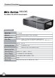
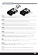
Product Overview ML06 The Mini-ITX HTPC benchmark Specification Model No. SST-ML06B Material 7mm aluminum front panel, 0.8mm steel body Motherboard Mini-ITX Drive Bay Exposed 9.5mm / 12.7mm slim slot-loading optical drive x 1 (replaceable with 3.5” HDD x 1 or 2.5” HDD x 2 or 120mm fan x 1) Cooling System 1 Internal 2.5” x 4 Right 2 x 80mm fan slot Top 120mm fan slot / oversized PSU vents Expansion Slot 1 Front I/O Port USB 3.
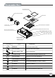
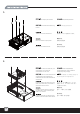
TOP FILTER (FF143) 2.5”HDD (NOT INCLUDED) TOP COVER 2.5”HDD CAGE MULTIPURPOSE4+IN-1BRACKET LOW PROFILE EXPANSION CARD(NOT INCLUDE) SFX PSU (SOLD SEARATELY) MOTHERBOARD(NOT INCLUDE) 8025 FAN X2 (NOT INCLUDE) USB 3.
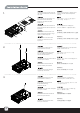
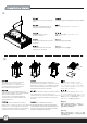
1. Unscrew the three screws from the rear of the chassis then remove the top cover. Отвинтите три винта с задней части корпуса, затем снимите верхнюю крышку.. Lösen Sie die drei Schrauben von der Rückseite des Gehäuses, entfernen Sie dann die obere Abdeckung. 케이스 뒷편의 3개의 나사를 풀은뒤 상부 커버를 제거합니다. Dévissez les trois vis à l'arrière de boîtier et ensuite retirez le panneau supérieur.
4. Install power supply into the case. Please note the case supports mounting power supply in two different orientations. If you use SilverStone’s SFX power supply, you must install it with the 80mm fan facing up. (For more information regarding power supply size limitations, please refer to the component guide in later pages) Installieren Sie das Netzteil im Gehäuse. Bitte beachten Sie, dass das Gehäuse die Montage des Netzteils in zwei verschiedenen Ausrichtungen unterstützt.
5. Remove the multipurpose bracket. Nehmen Sie die Mehrzweckhalterung heraus. Снимите многоцелевой кронштейн. 다목적 브래킷을 분리합니다. Retirez le crochet multifonction. 多目的ブラケットを取り外します。 Retire el bracket multipropósito. 拆卸多功能磁架 Rimuovere la staffa multiuso. 拆卸多功能磁架 Insert the I/O shield included with your motherboard, then install the motherboard into the case. Установите панель ввода/вывода материнской платы, затем установите материнскую плату в корпус.
7. We recommend at this point to start thinking about routing the cables cleanly before connecting them to the motherboard, cables include fan cables, power supply 24pin cable, CPU ATX 4pin/EPS12V 8pin, front panel connectors, front I/O connectors, and USB 3.0 connector.
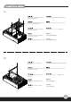
. Install and secure required expansion cards. Установите и закрепите необходимые платы расширения. Installieren und befestigen Sie die erforderlichen Erweiterungskarten. 필요한 확장카드를 설치하고 고정시킵니다. . Installez et fixez les cartes d'extension requises. 必要とされる拡張カードをインストールし、 固定します。 Instale y fije las tarjetas de expansión necesarias. 移除介面卡檔片,安裝介面卡 Installare ed assicurare le schede di espansione necessarie. 移除适配卡档片,安装适配卡 繁體中文 简体中文 10. Depending on requirement, install either slim optical drive, a 3.
11. Reinstall the multipurpose bracket back into the chassis. Установите многоцелевой кронштейн в корпус. Bauen Sie die Mehrzweckhalterung wieder in das Gehäuse ein. 다목적 브래킷을 섀시에 도로 설치합니다. . Réinstallez le crochet multifonction à l'arrière du châssis. 多目的ブラケットをケースに戻します。 Reinstale el bracket multipropósito de nuevo en el chasis. 將多功能磁架裝回機殼 繁體中文 简体中文 Reinstallare la staffa multiuso nel telaio. 将多功能磁架装回机壳 12. Reinstall center brace back into the case. Установите центральную скобу обратно в корпус.
13. Place the top cover back onto the case and secure with three screws to complete installation. Platzieren Sie die obere Abdeckung auf dem Gehäuse und befestigen Sie sie zum Abschluss der Installation mit drei Schrauben. Remettez le panneau supérieur sur le boîtier et fixez le avec trois vis pour terminer l'installation. Vuelva a poner la cubierta superior en la carcasa y fíjela con tres tornillos para completar la instalación.
Connector definition (1) Front panel connector installation Power switch and reset switch installation guide: Please refer to the motherboard manuals for the motherboard’s “Front Panel Connector” or “System Panel Connector” pin definition. Power switch and reset switch have no polarity, so they can be connected in any orientation.
Connector definition Please refer to the motherboard : manuals for the motherboard’s “Front Panel Connector ” or “System Panel Connector” pin definition.; the white/black wires are negative while other colors are positive wires. The Power LED wires are separate pins for compatibility with different motherboard so please make sure they are connected in the right polarity by referring to your motherboard manual.
Front I/O connector guide Below are the front I/O connectors pin definition, please also check your motherboard manual to cross reference with motherboard’s front I/O pin headers. SilverStone’s I/O connectors are in block type to simplify installation. Nachstehend finden Sie die Pinbelegung der vorderen E/A-Anschlüsse; bitte gleichen Sie zudem das Handbuch Ihres Motherboards mit den vorderen E/A-Pinzuweisungen ab. SilverStones E/A-Anschlüsse befinden sich zur Vereinfachung der Installation in Blockart.
Component size limitations The ML06 was designed to be as small as possible while maximizing interior space usage, please refer to the following guidelines for component selection and future upgrade considerations. (1) CPU cooler height limitation CPU Cooler height limitation will vary depending on the component installed on the multipurpose bracket. Please refer to the table below. Die maximale Höhe des CPU-Kühlers hängt davon ab, welche Komponenten in der Mehrzweckhalterung installiert wurden.
35.6 120.0 34 28 102 18.7 138.7 130 Please note 3.5” hard drive and 120mm x 25mm fan are thicker and might interfere with USB 3.0 connector. 3 1 2 Component size limitations (2) Power supply limitations The ML06 supports standard SFX power supply with a 100mm depth. Der ML06 unterstützt SFX-Standardnetzteile mit einer Tiefe von 100 mm. Le ML06 supporte une source d'alimentation SFX standard avec une profondeur de 100mm.
Component size limitations (3) Graphics card/expansion card length limitation The ML06 can accommodate low profile expansion cards up to 7.6” long. Standard low profile cards usually are only 6.6” long so the ML03 should fit nearly all types of low profile cards. Das ML06 Low-Profile-Erweiterungskarten mit einer Länge von bis zu 19,3 cm aufnehmen. Standard-Low-Profile-Karten sind üblicherweise nur 16,76 cm lang - dadurch passen nahezu alle Arten von Low-Profile-Karten in das ML05.
ML06はスリムタイプ「スロットローディング」光学ドライブのみをサポートします。 下図は、12.7mmと9.5mmの光学ドライブの例です。 ML06 只能使用吸入式薄型光碟機。 以下是12.7mm與9.5mm的光碟機範例供您做參考。 ML06 只能使用吸入式薄型光驱。 以下是12.7mm与9.5mm的光驱范例供您做参考。 Upgrade and maintenance (1) Fan filter removal guide Picture: An example of a PSU that has malfunctioned due to it overfilled with dust. To ensure long and optimal use of the installed PSU, we recommend cleaning the PSU filters regularly every three months or half a year (depending on your environment).
Upgrade and maintenance The ML06 has an oversized CPU venting area on the top cover to ensure great cooling performance over the CPU area. If you require additional cooling, we recommend installing two low speed 80mm fans such as SilverStone’s SUSCOOL81 to the right side of the case. You can purchase additional FF81 filter to prevent dust from entering the chassis. Das ML06 verfügt zur Optimierung der Kühlleistung oberhalb der CPU über eine überdimensionierte CPU-Belüftungsfläche an der oberen Abdeckung.
Situato nei pressi del primo slot di espansione, troviamo un pre taglio della forma di un connettore VGA (D-sub), è stato progettato per poter salvare uno slot di espansione che sarebbe stato occupato da una VGA low profile in configurazione dual slot. Si raccomanda di selezionare una scheda video con una configurazione singolo alloggio a basso profilo per sfruttare il vano VGA (D-sub) implementato in ML06.
Installation steps 1. Use a hex screwdriver to remove the standard sized slot from the graphics card. 2. Break the VGA (D-sub) cutout from the case and install the VGA (D-sub) connector. The case’s cutout supports mounting of the connector in both orientations so you may choose one that best suit your graphics card’s requirement. 1. Entfernen Sie mit einem Sechskantschraubendreher den Standardsteckplatz von der Grafikkarte. 2.
Warranty Information This product has a limited 1 year warranty in North America and Australia. For information on warranty periods in other regions, please contact your reseller or SilverStone authorized distributor. Warranty terms & conditions 1. Product component defects or damages resulted from defective production is covered under warranty. Defects or damages with the following conditions will be fixed or replaced under SilverStone Technology’s jurisdiction.
G11220140