NIGHTJAR SERIES SST-ST45NF Optimum fan-less power supply with stability and silence
SilverStone Nightjar ST45NF ATX12V 2.3 Switching Power Supply With Active PFC PS/2 450W This specification describes the electrical characteristics, functional and physical of a PS/2 Fanless Switching power supply; the maximum output shall be 450W when Input Voltage is from 100V to 240V. This power supply is also design with Active PFC (Power Factor Correction) capabilities. 2.1.
SST-ST45NF 2.3. Input Power Factor Correction ( Active PFC) Š 0.95 at nominal input voltage. The power factor at full load shall be Ŀ 2.4. Input Current Harmonics When the power supply is operated in 99-264Vac of Sec. 2.1, the input harmonic current drawn on the power line shall not exceed the limits set by EN61000-3-2 class "D" standards. The power supply shall incorporate universal power input with active power factor correction. 2.5.
2.9. Electro Static Discharge, IEC61000-4-2 In addition to IEC61000-4-2, the following ESD tests should be conducted. Each surface area of the unit under test should be subjected to twenty (20) successive static discharges, at each of the follow voltages: 2KV, 3KV, 4KV, 5KV, 6KVand 8KV. All power supply outputs shall continue to operate within the parameters of this specification, without glitches or interruption, while the power is operating as defined and subjected to 2kV through 10kV ESD pulses.
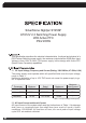
SST-ST45NF O 450W /25 C at 180Vac ~264Vac Output Voltage +3.3V +5V +12V -12V +5VSB Max. Load 22A 15A 35A 0.5A 2.5A Min. Load 0A 0A 0A 0A 0.5A 40A 0A 0A 0A 3.5A Peak Power Table 5 - High Load Range 1: Note Note Note Note 1: The +5 & +3.3 Volt total output shall not exceed 130 W. 2: The +5, +3.3 & +12Volt total output shall not exceed 430W. 3: Maximum continues total DC output power should not exceed 450W 4: Peak Power should not exceed 500W 3.2.
3.3. Dynamic Loading The output voltages shall remain within the limits specified in Table 7 for the step loading and within the limits specified in Table 8 for the capacitive loading. The load transient repetition rate shall be tested between 50Hz and 5kHz at duty cycle ranging from 10%-90%. The load transient repetition rate is only a test specification. The Δstep load may occur anywhere within the MIN load to the MAX load shown in Table 5 and Table 6. Output +5V +3.
SST-ST45NF Figure 1 : Output Voltage Timing Item Tsb_on-delay Description Delay from AC being applied to +5VSB being within regulation. MIN - MAX Units 1500 mS Tac_on-delay Delay from AC being applied to all output voltages being within regulation. - 2500 mS Tvout_holdup Time all output voltage stay within regulation after loss of AC at 115V and 230Vac, Full load.
+5VSB Figure 2 : Turn On/Off Timing 3.6. Power Good Signal : PWOK PWOK is a power OK signal and will be pulled HIGH by the power supply to indicate that all the outputs are within the regulation limits of the power supply. When any output voltage falls below regulation limits or when AC power has been removed for a time sufficiently long so that power supply operation is no longer guaranteed, PWOK will be deserted to a LOW state. See for a representation of the timing characteristics of PWOK.
SST-ST45NF 3.7. Remote On/Off Control : PSON# The PWON# signal is required to remotely turn on/off the power supply. PSON# is an active low signal that turns on the +5V, +3.3V, +12V and -12V power rails. When this signal is not pulled low by the system, or left open, the outputs (except the +5VSB and Vbias) turn off. This signal is pulled to a standby voltage by a pull-up resistor internal to the power supply. Signal Type Accepts an open collector/drain input from the system.
4.1. Over Current Protection This power supply shall have current limit to prevent the +5V, +3.3V, and +12V outputs from exceeding the values shown in table 14. The current limit shall not trip under maximum continuous load or peak loading as described in Table 5. The power supply shall latch off if the current exceeds the limit. The latch shall be cleared by toggling the PSON# signal or by cycling the AC power. The power supply shall not be damaged from repeated power cycling in this condition.
SST-ST45NF 5.1. Temperature o o o o Operating Temperature Range 0 C ~ 25 C (32 F~ 75 F) Non-Operating Temperature Range -40 C ~ 70 C (-40 F~ 158 F) o o o o 5.2. Humidity Operating Humidity Range 20% ~ 90%RH non-condensing Non-Operating Humidity Range 5% ~ 95%RH non-condensing 5.3. Altitude Operating Altitude Range Sea level to 10,000 ft Non-Operating Altitude Range Sea level to 40,000 ft 5.4.
6.1. Safety Certification Product Safety UL 60950-1, IEC60950 TUV, BSMI ,CCC RFI Emission FCC Part15 (Radiated & Conducted Emissions) CISPR 22,3rd Edition/ EN55022 Class B) PFC Harmonic EN 61000-3-2 Flicker EN 61000-3-3 Immunity against: -Electrostatic discharge: EN55024: 1998 -IEC 61000-4-2 Min. 4kV contact discharge Min. 8kV air discharge -IEC 61000-4-3 Min.
SST-ST45NF 7.1. Mean Time Between failures (MTBF) The MTBF of the power supply shall be calculated utilizing the Part-Stress Analysis method of Bellcore MIL217F. The calculated MTBF of the power supply shall be greater than 100,000 hours under the following conditions: o (a)Full rated load, (b)120V AC input ,(c)Ground Benign;(d) 25 C 8.1.
9.1. Weight: 2.8Kg (TBD) 9.2. Power Supply Dimension: 150mm(W) x 86mm(H) x 160mm(D) 9.3. Connectors (Pin definition) M/B 24PIN connector 18AWG wire Signal Pin Orange +3.3V 13 Pin Signal 18AWG wire 1 +3.3V Orange Orange(22AWG) +3.3Vsense 13 Blue (18AWG) -12VDC 14 2 +3.
February, 2008 NO:G11205490