
User's Manual


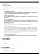


Table Of Contents

06
Time Diagram
Figure 1
* T1 : Turn on time ( 500mS Max.)
* T2 : Rise time ( ≦ 20mS Max.)
* T3 : Power good turn on delay time ( 100 < T3 < 500 mS )
* T4 : Switch on time (10mS Max.)
* T5 : Power hold-on time ( 16 mS Min at 70%load)
* T6 : Power good turn off delay time ( 1.0 mS Min.)
* Power on-off cycle :
When the power supply is turned off for a minimum of 2.0 sec. and turn on again, the power good signal
will be asserted.
The power supply with active power factor correction, and meet the EN61000-3-2
standards, The power factor is greater than 0.9 at 230V/50Hz, Max. load.
13. Power Factor
150 mm (W) × 86 mm (H) × 140mm (D)
14. Mechanical Specification
The MTBF of the power should be 100,000 hours min.
10. MTBF
11.1 Input Voltage
Applying 220Vac.
11.2 Test Condition
Applying 75% loads for the power supply in 45 (+/-5) C chamber for 4 hours.
11. Burn-In
The product shall meet requirement for EN61000-3-2 & EN61000-3-3 :1995 standard
of class D, test at 230Vac 50Hz.
12. Harmonics
Power Supply Timing