TJ11 October, 2010 NO: G11212980
Installation and system optimization guide: The following manual and guides were carefully prepared by the SilverStone engineering team to help you maximize the potential of your SilverStone product. Please keep this manual for future reference when upgrading or performing maintenance on your system. A copy of this manual can also be downloaded from our website at: http://www.silverstonetek.com 1 Specification P.2 Disassemble chart P.3 Installation guide P.5 Connector definition P.
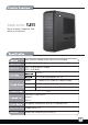
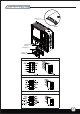
Temjin series TJ11 Tower of power, elegance, and technical excellence Dual aluminum unibody frame, 2.0mm aluminum body SSI CEB, XL ATX, ATX (maximum 13.6” x 11”), Micro ATX Model No. SST-TJ11B-W (black + window) SST-TJ11B (black) 5.25" x 9 3.5" x 6 hot-swap capable , 2.5” x3 Bottom 2 x 120mm AP121 intake fan, 1200rpm 19dBA Top 1 x 120mm exhaust fan, 900rpm, 18dBA Side 2 x 180mm AP181 intake fan, 700/1200rpm 18/34dBA 9+1 USB 3.0 x 2, USB 2.
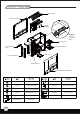
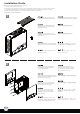
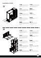
TOP COVER LEFT SIDE PANEL ATX MB (OPTION) FRONT I/O USB 2.0 x 2, AUDIO x 1, MIC x 1 18032 FAN x 2 SILVERSTONE CP05 18032 FAN FILTER x 2 PSU x 2 3.5” HDD Tray 5.25” DRIVE BAY x 9 3.5” DRIVE BAY x 6 RIGHT SIDE PANEL-WINDOW SCREW A SECURE 5.25" DRIVE ALUMINUM-PLATE MOUSE PAD SCREW B SECURE HARD DRIVE 2.5” HDD BKT SECURE 2.
USB 3.0 x 2 RESET SILVERSTONE CP05 x 6 12025 FAN x 2 12025 FAN FILTER x 2 USB 2.
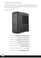
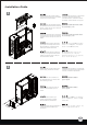
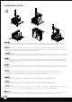
lnstallation Guide Before you begin, please make sure that you (1) have all components collected. (2) check that all components do not have compatibility problems with each other or with the case. (3) if possible, assemble the components outside the case first to make sure they are working. (4) keep the motherboard manual ready for reference during installation. (5) prepare a Philips screwdriver. 1 Pull top cover off the case in the direction as illustrated by the arrow.
lnstallation Guide 3 Loosen four thumb screws holding Отвинтите четыре винта с накатанной the motherboard tray then pull upward головкой, крепящие кронштейн to slide it out of the chassis. системной платы, а затем потяните его вверх, чтобы извлечь из корпуса. Lösen Sie die vier Rändelschrauben 先鬆開鎖固主機板抽盤的4顆手扭螺絲, des Motherboard-Einschubs; entfernen 將主機板抽盤往上抽出。 Sie ihn, indem Sie ihn nach oben aus dem Gehäuse ziehen.
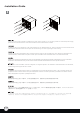
lnstallation Guide 5 Install one or two power supplies as needed to the power supply bracket. If you are using a PS/2 mini redundant power supply, please use the included PS/2 mini redundant bracket from the accessories box instead. Installieren Sie je nach Bedarf ein oder zwei Netzteile an der Netzteilhalterung. Bitte verwenden Sie beim Einsatz eines redundantes PS/2-Mininetzteil die entsprechende Halterung aus dem zugehörigen Lieferumfang.
lnstallation Guide 6 Install power supply back into the chassis with bracket attached, then secure with screws removed from step 4. Установите блок питания в корпус с прикрепленным кронштейном, а затем закрепите его винтами, удаленными на шаге 4. Installieren Sie das Netzteil mit der Halterung im Gehäuse; befestigen Sie es mit den Schrauben, die Sie in Schritt 4 gelöst haben.
lnstallation Guide 8 2 1 3 Remove expansion slot covers as required then install expansion cards onto the motherboard. If you have a graphics card that will take up the space beyond the 9th expansion slot, you will then need to remove the reinforcement end-plate below the 9th expansion slot. Entfernen Sie die Blenden der benötigten Erweiterungssteckplätze; installieren Sie die Erweiterungskarten dann am Motherboard.
lnstallation Guide 9 Slide the entire assembled motherboard tray back into the chassis and secure with four thumb screws. Задвиньте кронштейн с материнской платой в полном сборе в корпус и закрепите его винтами с накатанной головкой. Schieben Sie die gesamte Motherboard-Baugruppe zurück in das Gehäuse; befestigen Sie sie mit vier Rändelschrauben. 將主機板抽盤裝回機殼, 鎖回4顆手扭螺絲。 Faites glisser la carte mère assemblé à son support à l'intérieur du boîtier et fixez l'ensemble avec les quatre vis à main.
lnstallation Guide 11 Insert optical drives or other 5.25” devices into the drive bays and secure with screws. Установите оптические приводы или другие 5,25-дюймовые устройства в отсеки для приводов и закрепите их винтами. Stecken Sie ein optisches Laufwerk oder andere 5,25 Zoll-Geräte in die Laufwerkseinschübe; befestigen Sie sie mit Schrauben. 將光碟機裝入機殼,用螺絲鎖固。 Insérez les lecteurs optique ou d'autres appareils 5.25” dans leurs baies et fixez-les avec des vis.
lnstallation Guide 14 Insert assembled hard drive tray back into the chassis. If you are not using a standard 3.5” SATA hard drive, you will need to remove the CP05 SATA connector on the other side of the hard drive cage. To do this you will need to first remove the fan on the hard drive cage to get to the screws holding the CP05. Installieren Sie den montierten Festplatteneinschub wieder im Gehäuse.
lnstallation Guide 15 Insert the 2.5” hard drives or SSD into the 2.5” drive tray as shown in the illustration. Установите 2,5-дюймовые жесткие диски или SSD-диски в кронштейн для 2,5-дюймовых приводов, как показано на рисунке. Stecken Sie die 2,5 ZollFestplatten oder SSD in den 2,5 Zoll-Festplatteneinschub (vgl. Abbildung). 請將2.5”硬碟依圖示放入2.5”硬碟架。 Insérez les disques durs 2.5” hard drives ou les SSD sur le support à disques 2.5” comme montré sur l'illustration. 请将2.5”硬盘依图标放入2.5”硬盘架。 図示されるように、2.
lnstallation Guide 17 18 Use screw A to install and secure the assembled 2.5” drive tray onto the chassis. Установите и с помощью винтов (A) закрепите кронштейн с 2,5-дюймовыми дисками в сборе на корпусе. Installieren Sie den montierten 2,5 Zoll-Festplatteneinschub mit Schraube A im Gehäuse. 請依圖示用SCREW A, 將2.5”硬碟架鎖固於機身。 Utilisez les vis de type A pour installer et fixer les lecteurs assemblés à leurs support dans le boîtier. 请依图标用SCREW A, 将2.
lnstallation Guide 19 Remount the top cover back onto the chassis to complete installation. If you need to move the completed build to another location please have another person help you as a completed TJ11 build will be very heavy. Befestigen Sie zum Abschluss der Installation die obere Abdeckung wieder am Gehäuse Wenn Sie den Standort des gesamten Gerätes ändern möchten, lassen Sie sich bitte von einer weiteren Person helfen; ein zusammengebautes TJ11 ist sehr schwer.
Connector definition (1) Front panel connector installation Power switch and reset switch installation guide: Please refer to the motherboard manuals for the motherboard’s “Front Panel Connector” or “System Panel Connector” pin definition. Power switch and reset switch have no polarity, so they can be connected in any orientation.
Connector definition LED connector installation guide: Please refer to the motherboard manuals for the motherboard’s “Front Panel Connector” or “System Panel Connector” pin definition.;the white wires are negative while other colors are positive wires. The Power LED wires are separate pins for compatibility with different motherboard pin definition so please make sure they are connected in the right polarity by referring to your motherboard manual.
Front I/O connector guide Below are the front I/O connectors pin definition, please also check your motherboard manual to cross reference with motherboard’s front I/O pin headers. SilverStone’s I/O connectors are in block type to simplify installation. Nachstehend finden Sie die Pinbelegung der vorderen E/A-Anschlüsse; bitte gleichen Sie zudem das Handbuch Ihres Motherboards mit den vorderen E/A-Pinzuweisungen ab. SilverStones E/A-Anschlüsse befinden sich zur Vereinfachung der Installation in Blockart.
Component size limitations The TJ11 can accommodate all standard size components and even some that are out of spec, please refer to the following guidelines for component selection and future upgrade considerations: (1) CPU cooler height limitation If you like to install the CPU cooler with the motherboard tray outside of the chassis, the height limit is 165mm and there is 10mm of clearance around the motherboard to allow the motherboard tray to be slid back into the chassis.
Component size limitations If you are installing the CPU cooler with the motherboard tray already inside the chassis, the height limitation is increased to 171mm with 42mm of clearance beyond the motherboard. If there are still interference, you can remove the reinforcement end-plate from the motherboard tray. Wenn Sie den CPU-Kühler installieren möchten, während sich der Motherboard-Einschub bereits im Gehäuse befindet, beträgt die maximale Höhe 171 mm mit einem Abstand von 42 mm rund um das Motherboard.
Component size limitations (2) Power supply limitations There are no limitations for power supply depth. However, if you intend to use two large power supplies such as the SilverStone’s ST1500 (220mm deep), you may need to remove one of the hard drive cages in order to free up additional room for routing cables through the middle of the case.
Component size limitations Below is a table of recommend cable length based off of common retail power supplies. Please make sure that the power supply you want to use has long enough cables to fit the below recommendations or you can also choose to purchase additional power cable extensions: Nachstehend finden Sie eine Tabelle der empfohlenen Kabellänge basierend auf handelsüblichen Netzteilen.
Component size limitations (3) Graphics card/expansion card length limitation The TJ11 can support consumer level graphics cards up to 12.4 inches long. Graphic card length reference: AMD Radeon HD 5970 – 12.2 " 12.4 inches long AMD Radeon HD 5870 – 11” NVidia Geforce GTX480 – 10.5” AMD Radeon HD 5850 – 9.5”” NVidia Geforce GTX470 – 9.
Хотя корпус TJ11 не предназначен для материнских плат форм-фактора Extended-ATX, размер внутреннего пространства все же позволяет устанавливать материнские платы шириной до 11 дюймов. Кроме того, кронштейн материнской платы оснащен крепежными выступами для поддержки двухпроцессорных материнских плат SSI-CEB. Ширина высококлассных материнских плат, таких как ASUS Rampage III Extreme и EVGA X58 Classified 4-Way SLI, составляет 10,6 и 10,375 дюйма, соответственно.
Component size limitations New generation of SSI-CEB server or workstation motherboards no longer require CPU cooler mounting holes on the motherboard tray. Coolers can now be installed directly on the motherboard. As a result, we eliminated support for SSI-CEB CPU cooler mounting holes and instead increased the large gap on the motherboard tray to support CPU cooler back plates swapping with more LGA 1156/1155 motherboards.
新一代SSI-CEB規格伺服器主機板,已經沒有依照SSI規範的Xeon Cooler在機殼上的鎖固孔位,其Cooler本身是鎖在主機板上。我們新一代的機殼 為了配合LGA1156/1155的位置,將主機板底板對應的開孔加大,因而取消了SSI規範上的Cooler鎖固螺柱。並不是不相容於SSI CEB主機板,只是 因應主機板規格的演進而修改設計。 新一代SSI-CEB规格服务器主机板,已经没有依照SSI规范的Xeon Cooler在机壳上的锁固孔位,其Cooler本身是锁在主机板上。我们新一代的机壳 为了配合LGA1156/1155的位置,将主机板底板对应的开孔加大,因而取消了SSI规范上的Cooler锁固螺柱。并不是不兼容于SSI CEB主机板,只是 因应主机板规格的演进而修改设计。 新世代のSSI-CEBサーバまたはワークステーションマザーボードは、マザーボードトレイ上のCPUクーラー設置孔をもはや必要としていません。 クーラーは現在直接マザーボードに装着できます。結果として、弊社はSSI-CEB CPUクーラー設置孔サポートをやめ、代わりに、より多くの LGA1156/1155マザーボードと互換性のある
Component size limitations (5) Optical drive length limitation and 10th expansion slot When the 10th expansion slot space is used, the maximum length for optical drive is 240mm. В случае использования пространства 10-го слота расширения максимальная длина оптического привода составляет 240 мм. Falls der zehnte Erweiterungssteckplatz genutzt wird, liegt die maximale Länge eines optischen Laufwerks bei 240 mm.
Recommended cooling device setup and selection If you are installing a tower-style CPU cooler, we recommend that the CPU fan blows upward to work with TJ11’s overall airflow. Если вы устанавливаете башенный кулер ЦП, то мы рекомендуем установить его таким образом, чтобы воздушный поток вентилятора ЦП был направлен вверх и совпадал с общим направлением воздушного потока внутри корпуса TJ11.
Recommended cooling device setup and selection BLACK YELLOW (H) RED (L) 180mm fan switch guide“L” indicates low speed state, “H” indicates high speed state. TJ11’s two main Air Penetrator AP181 fans are speed adjustable in two speeds, 700rpm or 1200rpm. The speeds are designed for silent or performance usage. Die Geschwindigkeit der beiden Hauptlüfter (Air Penetrator AP181) des TJ11 kann angepasst werden: 700 U/min oder 1200 U/min.
Recommended cooling device setup and selection SilverStone also has three models of 180mm for sale separately for replacement or upgrade: SilverStone bietet zudem drei Modelle der 180 mm-Lüfter zum separaten Verkauf; mit diesen können Sie Ihr System aufrüsten oder alte Lüfter ersetzen: SilverStone vend aussi trois modèles de ventilateur de 180mm pour le remplacement ou une amélioration: SilverStone también tiene tres modelos de 180mm a la venta por separado como reemplazo ó mejora: Silverstone ha in ca
Upgrade and maintenance (1) Fan removal guide If you need to replace, clean, or upgrade the fan, please follow the steps below. 1 2 Slide motherboard tray out of the chassis. Выдвиньте кронштейн материнской платы из корпуса. Entfernen Sie den MotherboardEinschub aus dem Gehäuse. 先移除主機板抽盤。 Faites glisser le porte-carte mère hors du châssis. 先移除主机板抽盘。 Deslice la bandeja de la placa base hasta sacarla del chasis. ケースからのマザーボードトレイ をスライドさせて取り出します。 Rimuovere il supporto scheda madre dal case.
Upgrade and maintenance 3 Remove fan mounting screws to remove the fans for cleaning or replacement. Lösen Sie die Montageschrauben des Lüfters, wenn Sie diesen reinigen oder ersetzen möchten. Pour déposer les ventilateurs, les nettoyer ou les remplacer, retirez les vis de montage de chaque ventilateur. Quite los tornillos de la estructura del ventilador para retirar los ventiladores para su limpieza ó reemplazo. Rimuovere le viti delle ventole per asportarle a scopo di pulizia o sostituzione.
Upgrade and maintenance 4 BLACK YELLOW (H) RED (L) Install fans back onto the fan bracket and secure with screws. Install the fan switches back onto the top panel, make sure the switch orientation matches the “H” and “L” (high and low speeds) markings correctly then secure with screws. Installieren Sie die Lüfter wieder an der Lüfterhalterung; befestigen Sie sie mit Schrauben.
Upgrade and maintenance An example of a GPU cooler that is filled with dust and has lost most of its cooling performance TJ11’s positive air pressure design is an effective configuration that will reduce dust buildup inside the case. Small air particles or lint will accumulate over time on intake filters instead of on the components inside the case.
Upgrade and maintenance A For 180mm fan filters, please remove them as shown. Bitte entfernen Sie die Filter der 180 mm-Lüfter wie in der Abbildung gezeigt. Pour les filtres de ventilateur de 180 mm, veuillez les retirer comme illustré. Para los filtros de los ventiladores de 180mm, por favor retírelos como se muestra. Per le ventole da 180mm, rimuovere i filtri come mostrato. Удалите фильтры 180-мм вентиляторов, как показано.
Upgrade and maintenance B For 120mm hard drive fan filters, after removing left side panel, use a screw driver to remove screws holding the 120mm fan filter (the fan will also come off at the same time). 120 mm-Festplattenlüfter: Lösen Sie nach dem Entfernen der linken seitlichen Blende mit einem Schraubendreher die Schrauben des 120 mm-Lüfterfilters (der Lüfter wird dadurch ebenfalls gelöst). Pour le filtre de ventilateur du disque dur de 120 mm, retirez le panneau gauche.
Upgrade and maintenance C There are two FF141 magnetized fan filters included in the accessories box, you may use them to attach directly on the power supplies. Im Lieferumfang sind zwei magnetisierte Lüfterfilter (FF141) enthalten; Sie können diese direkt an den Netzteilen anbringen. Deux filtres de ventilateur magnétisés FF141 sont inclus dans la boîte à accessoires. Vous pouvez les utiliser en les fixant directement sur les blocs d'alimentation.
Upgrade and maintenance ClearCMOS TJ11 supports SST-CLEARCMOS installation on a designated part of the case, please see example below: Das TJ11 unterstützt die SST-CLEARCMOS-Installation an einem dazu vorgesehenen Teil des Gehäuses; bitte halten Sie sich an das nachstehende Beispiel: Le TJ11 est compatible avec l'installation du SST-CLEARCMOS dans une partie spéciale du boîtier, voici un exemple ci-dessous: La TJ11 acepta la instalación de SST-CLEARCMOS en una parte dedicada a ello en la carcasa, por fa
Upgrade and maintenance SATA hot-swap All six 3.5” hard drive bays have CP05 hot-swappable adapter included. Please note the following points if you decide to utilize the hot-swap functionality: A. If you need to swap hard drives while running an operating system (hot-swap), you need to make sure the SATA chipset (or motherboard southbridge) used to connect to hard drives has proper support and driver to do so.
Все шесть отсеков для 3,5-дюймовых жестких дисков оснащены адаптером CP05 для «горячего» подключения. Если вы собираетесь использовать функцию «горячего» подключения, следует учитывать перечисленные ниже факторы: A. Если вам надо подключить жесткие диски при запущенной операционной системе (горячее подключение), убедитесь, что чипсет SATA (или южный мост материнской платы), используемый для подключения жестких дисков, поддерживает эту возможность, и нужный драйвер установлен.
Useful information for modding 15 28 C. B. 1.68 Motherboard 7 Motherboard R35 154 630 204 please note that any cutting, drilling, or irreversible modification on the chassis will void your warranty, the information provided below is not an endorsement from SilverStone to mod or alter your chassis. A. If you need to utilize the entire lower compartment of TJ11, the drive cages can be easily removed and reinstall into the 5.25” drive bays on the front panel. Each drive cage will take up three 5.
Полезная информация о моддинге. (Следует учитывать, что резка, сверление и любая необратимая модификация корпуса приведет к аннулированию гарантии. Приведенная ниже информация не является одобрением компании SilverStone на модификацию или изменение корпуса.) A. При необходимости использования всего нижнего отсека корпуса TJ11 кронштейны жестких дисков можно легко удалить и установить в отсеки для 5,25-дюймовых дисков на передней панели.