
User guide

on the remote control to activate the automatic adjustment function. If the automatic
procedure fails to achieve the required effect, enter the Frequency and Phase values
manually and move sufficiently close to the screen to observe the effects of the
adjustments.
Y/C Delay
Where Video signals are concerned, use this adjustment to correct horizontal color
misalignment within the projected image. For a given video standard (for example PAL
or NTSC) the stored value does not normally require further adjustment, unless the
source or connection cable is changed.
Signal Range
Determines the signal data range of HDMI signals. It is available when the HDMI signal
comes from a RGB source or when the AVI (Auxiliary Video Information) infoframe of
the HDMI signal is missing or inconsistent.
• Auto determines the signal range using the information provided by the AVI
infoframe of the HDMI signal. If the AVI infoframe is missing or incosistent, the
projector uses values 0-255. Auto (which is the default setting) usually selects
the correct signal range but you can force either 16-235 or 0-255
• 16-235 sets black at R, G, B = 16 and white at R, G, B = 235, to match the
luminance values of digital component standards
• 0-255 sets black at R, G, B = 0 and white at R, G, B = 255
Lamp Power
Use this control to adjust the lamp output level in 10 W increments from 230 W to
280 W. Lower values decrease brightness but extend the life of the lamp.
Setup
This menu section provides access to installation adjustments.
Orientation
Selects the orientation of the projected image. Available settings are: Floor, Ceiling,
Floor Rear and Ceiling Rear.
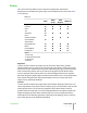
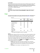
Keystone
This adjustment compensates the distortion resulting from the angle of projection.
Note: Keystone may cause artifacts in the image and may not be available when
displaying specific 3D content (see Table 4.2). SIM2 recommends that you use this
feature only when necessary.
RGBS Sync
This setting indicates where the sync relative to the RGB signal is supplied. Choose:
• HV when the HV connector is used for the RBGS sync signal
• Video when the RGB sync signal originates from a SCART outlet (via the
SCART/R-G-B-sync conversion cable). In this case the R, G and B signals are
connected to the specific RCA connectors and the sync signal is connected to
the Video input
Projection Lens
4 Operation SUPERLUMIS
User Guide
30