
Manual


310LP Phono Preamplifier
____________________________________________________________________________________
10
One of the five jumper sockets for each channel
must always have a jumper inserted into it,
otherwise the 310LP will not produce an output
signal. As well, you should always maintain the
same resistance setting for both channels, otherwise
sound will vary between the left and right channels
of your audio system. Finally,
it is strongly
recommended that you never use the 47kΩ
resistive load setting for moving coil
cartridges.
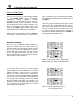
Capacitance Loading:
There are three (3) different settings available for
setting the capacitive load; 0pF, 100pF and 470pF
which are represented by jumper sockets J6, J7 and
J8 respectively for the left channel and jumper
sockets J24, J25 and J26 for the right channel (refer
to figure 4). The factory default setting is 100pF,
therefore jumpers will be found in sockets J7 & J25.
Figure 4: Left and right channel jumper banks
default setting for capacitance load adjustments
Typically, capacitance loading adjustments will only
impact the sonic performance of a MM cartridge. We
recommend that when using a MC cartridge, you
should set the capacitance load to 0pF by placing the
supplied jumpers into sockets J6 and J24,
respectively for the left and right channels. In the
event that you’re using a MM cartridge experiment
with the three (3) available loads, selecting the load
that provides the best possible sound quality. For
example, if you decided on using the capacitance
setting of 470pF, then you would insert the supplied
jumpers into sockets J8 and J26 (refer to figure 5
below).
Figure 5: Left and right channels
set to a 470pF capacitance load
One of the three jumper sockets for each channel
must always have a jumper inserted into it,
otherwise the 310LP will not produce an output
signal. As well, you should always maintain the
same capacitance setting for both channels,
otherwise sound quality may vary between the left
and right channels of your audio system.