
Manual


310LP Phono Preamplifier
____________________________________________________________________________________
11
Equalization Curve:
The MOON 310LP Phono Preamplifier is equipped
with circuitry for two (2) different equalization
curves; The RIAA standard and the less common IEC
modified curve. The main difference is that the RIAA
curve produces a flat frequency response from 20Hz
to 20kHz; The IEC curve acts as a subsonic filter
removing inaudible infrasonic bass below 20Hz.
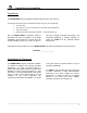
Figure 6: RIAA Equalization curve jumper setting
Jumper sockets J5 and J21, for the left and right
channels respectively, are used to set the 310LP’s
equalization curve. These jumpers sockets have three
pins allowing for 2 different possible positions. The
factory default position is for the RIAA curve as
shown in figure 6 where the jumper connects the
lower 2 pins. To select the IEC curve, place the
jumper over the upper 2 pins as shown in figure 7.
Figure 7: IEC Equalization curve jumper setting
To determine which curve you should use, do as
follows: with the 310LP set to the RIAA curve,
watch the movement of your loudspeaker’s bass
drivers – if their motion doesn’t follow the pattern of
the record currently playing and/or you see
excessive driver movement, chances are you should
use the IEC curve to eliminate the subsonic
information not present on the record.
Gain Setting:
There are four (4) gain settings available on the
MOON 310LP. They are 40dB for MM cartridges
and 54dB, 60dB and 66dB for MC cartridges.
However, keep in mind that when using the
balanced XLR outputs, each of these gain levels
increase by a factor of 6dB to 46dB, 60dB, 66dB and
72dB respectively (note: to keep the circuit board
labelling simple, only the single-ended RCA gain
levels are indicated).
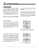
There are three (3) jumpers sockets for each channel
that are used to adjust the gain level setting; J16,
J17 and J18 for the left channel; J32, J33 and J34 for
the right channel. Each of these jumpers sockets
have three pins allowing for 2 different possible
positions. As well, there is a detailed diagram printed
on the circuit board, located just below and to the
right of each of these jumper banks, that shows the
jumper positioning for the four available gain settings
(see figure 8).
Figure 8: Left and right channel jumper
banks for gain level settings