
Owner`s manual


MOON 340i Integrated Amplifier
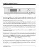
Rear Panel Connections (cont’d)
Below the area reserved for the optional digital inputs are a series of input/output connectors for custom type installations:
From left to right there are two (2) “SimLink” connectors labeled “in” and “out” on 1/8” mini jacks. Please refer to the next
section entitled SimLink™ for more details. Next, there’s a 1/8” mini-jack input for use with aftermarket infrared remote
control receivers. Then there’s a 12V trigger output on a 1/8” mini-jack that can power up a connected component (with a
12V trigger input) at the same time that the 340i is powered up. Finally, there’s a full-function bi-directional RS-232 port
control and status for custom integration or automation on a DB9 connector.
The MOON 340i is equipped with a pair of gold-plated binding posts. The right channel speaker output is located above the
analog inputs. The left channel speaker output is located to the right of the digital inputs. Connect your loudspeakers, with the
cables of your choice, to these binding posts, paying attention to respect the polarity (“+” , “-” ) of the output.
Finally on the far right side is the “AC Fuse” socket cover, the main power switch (“0”=off, “1”=on) and the IEC receptacle,
labeled “AC Power” for the included AC power cord.
You will notice that all RCA input and output connectors on the rear panel have been color coded: ‘white’ for the left channel
and ‘red’ for the right channel. A poor contact will degrade the signal substantially, and plugs and sockets should all look clean
and free of dirt and corrosion. The easiest way to clean them is to remove the cables from their sockets and push them back
in again. This procedure requires that your Integrated Amplifier and the rest of your components be completely turned off.
Not heeding this warning may result in serious damage to your equipment. Special contact cleaning fluids and enhancers
should not be used, as they deposit a difficult to remove residue which degrades the performance of your components.
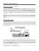
SimLink™
The SimLink™ provides communication features between various MOON components. For example, if you were to connect
the 360D to the 340i via the SimLink™, pressing the
X (play) button on the 360D will cause the 340i to automatically
switch to the input labeled ‘CD’. You can change this default setting as follows: Select the input that you want as the new
default for CD, then press and hold the ◄ INPUT (left) button until the front panel display begins to flash on and off.
Another feature of SimLink™ involves the “Standby” function. By pressing down and holding the “Standby” button for 2
seconds on the either the 360D or 340i, both units will go into “Standby” mode. The same logic applies when switching
from “Standby” to active mode.
In the event that you are using the MOON MiND Music Streamer and an external digital-to-analog converter (DAC), you
must make a SimLink™ connection between the MiND’s SimLink™ out and the 340i’s SimLink™ in. The ‘A1’ input is the
default input for your external DAC’s analog outputs; When you press the
X (play) button on the MiND App, the 340i will
automatically switch to the input labeled ‘A1’. If your 340i includes the “Digital Input” option, then the default input for the
MiND is the ‘D2” input; When you press the
X (play) button on the MiND App, the 340i will automatically switch to the input
labeled ‘D2’. You can change these default settings for the MiND as follows: Select the input that you want as the new
default for MiND, then press and hold the “MP” button until the front panel display begins to flash on and off.
The connection rules for the SimLink™ are very basic. You must always connect the supplied cable between one component’s
“SimLink™ Out” jack and another component’s “SimLink™ In” jack. If you inadvertently connect the cable between either two
“SimLink™ In” or two “SimLink™ Out” jacks, the SimLink™ communication feature will not function. Also, there is no master
component in a SimLink™ chain; no one particular component operates as the main communications controller.
____________________________________________________________________________________
Rear Panel Connections 12