
Owner`s manual


MOON i 5.3 Integrated Amplifier
Rear Panel Connections
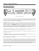
Figure 2: MOON i 5.3 Rear panel
The rear panel will look similar to Figure 2 (above). There are five (5) pairs of single-ended inputs on RCA connectors labeled
CD, A1, A2, A3 and A4. The left channel inputs are located on top and the corresponding right channel inputs are located
directly below. The A4 input, as previously mentioned, bypasses the gain stage and is intended to be used with a component,
such as a home theater processor, that has its own volume/gain control.
The MOON i 5.3 integrated amplifier has two pairs of non-amplified outputs; One single-ended pair of RCA connectors
labeled ‘Pre Out’, located next to the A4 input, is designated for output to a power amplifier with single-ended RCA inputs in
the event that you wish to use your MOON i
5.3 as a preamplifier only. The output level of the ‘Pre Out’ is dependant on the
volume control setting. A second single-ended pair if RCA connectors labeled ‘Tape Out’, located next to the ‘Pre Out’
connectors, is intended as an input to a recording device such as a cassette tape deck or CD-Recordable Player. Keep in mind
that the output level on the ‘Tape Out’ is fixed and cannot be adjusted by the i
5.3’s volume control. All RCA input and output
connectors on the rear panel have been color coded: ‘white’ for the left channel and ‘red’ for the right channel.
On each side of the group of RCA connectors, there is a pair of gold-plated binding posts. Connect your loudspeakers, with
the cables of your choice, to these binding posts. Take care to respect the polarity (“+” , “-” ) of the output.
Don’t hesitate to use high quality interconnects and speaker cables. Poor quality cables can degrade the overall sonic
performance of your system.
Your MOON i 5.3 is equipped with a 1/8” mini-jack input for use with aftermarket infrared remote control receivers. The “IR
in” connector is located on the far left side directly above the serial number information.
Finally on the right side is the main power switch (“0”=off, “1”=on), the IEC receptacle, labeled “AC Input” for the included
AC power cord, and the “AC Fuse” socket cover.
You will notice that all RCA input and output connectors on the rear panel have been color coded: ‘white’ for the left channel
and ‘red’ for the right channel. All rear panel connectors have been chosen because they provide the best possible
connections for your unit. A poor contact will degrade the signal substantially, and plugs and sockets should all look clean and
free of dirt and corrosion. The easiest way to clean them is to remove the cables from their sockets and push them back in
again. This procedure requires that your Integrated Amplifier and the rest of your components be completely turned off. Not
heeding this warning may result in serious damage to your equipment. Special contact cleaning fluids and enhancers should
not be used, as they deposit a difficult to remove residue which degrades the performance of your components.
____________________________________________________________________________________
Rear Panel Connections 9