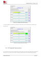
SIM7022-EVB User Guide V1.00 Feature 24: software download interface 6. After the update is successful, turn SW1 down to OFF state, then turn SW101 back to ON state, and then power on. Feature 25: software download complete 3.4 AT Command Communication AT commands currently have incomplete functions that need to be continuously updated after subsequent development. The content of this chapter is still being updated based on the actual debugging situation. www.simcom.
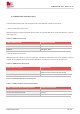
SIM7022-EVB User Guide V1.00 3.4.1UART Serial Communication The serial data frame format and serial baud rate of the SIM7022 module are as follows. 1. Set the serial data frame format SIM7022 supports multiple serial data frame formats. The default data frame format is 8 data bits, 1 stop bit, and no parity bit. Table 15: UART frame format UART frame format Supported formats Stop bit 1bit Parity bit Odd, Even, None Data bit 8bit,7bit 2.
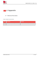
SIM7022-EVB User Guide V1.00 4 Appendix 4.1 Reference Documents Table 18: Reference documents Numb er File name Describe [1] SIM7022 Hardware Design SIM7022 Hardware Design Manual [2] SIM7022 Series_AT Command Manual SIM7022 AT Command Manual www.simcom.
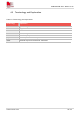
SIM7022-EVB User Guide V1.00 4.2 Terminology and Explanation Table 19: Terminology and explanation Terminology Explanation LED Light Emitting Diode LTE Long Term Evolution NC Not connect PSM Power saving mode RF Radio Frequency (U)SIM (Universal) Subscriber Identity Module UART Universal Asynchronous Receiver Transmitter www.simcom.
SIM7022-EVB User Guide V1.00 4.3 Safety Warning Table 20: safety warning Marks Requirements When in a hospital or other health care facility, observe the restrictions about the use of mobiles. Switch the cellular terminal or mobile off, medical equipment may be sensitive and not operate normally due to RF energy interference. Switch off the cellular terminal or mobile before boarding an aircraft. Make sure it is switched off.
OEM/Integrators Installation Manual Important Notice to OEM integrators 1. This module is limited to OEM installation ONLY. 2. This module is limited to installation in mobile or fixed applications, according to Part 2.1091(b). 3. The separate approval is required for all other operating configurations, including portable configurations with respect to Part 2.1093 and different antenna configurations 4. For FCC Part 15.
Antenna (1) The antenna must be installed such that 20 cm is maintained between the antenna and users, (2) The transmitter module may not be co-located with any other transmitter or antenna. In the event that these conditions cannot be met (for example certain laptop configurations or co-location with another transmitter), then the FCC authorization is no longer considered valid and the FCC ID cannot be used on the final product.
Federal Communication Commission Interference Statement This device complies with Part 15 of the FCC Rules. Operation is subject to the following two conditions: (1) This device may not cause harmful interference, and (2) this device must accept any interference received, including interference that may cause undesired operation. This equipment has been tested and found to comply with the limits for a Class B digital device, pursuant to Part 15 of the FCC Rules.
This device is intended only for OEM integrators under the following conditions: (For module device use) 1) The antenna must be installed such that 20 cm is maintained between the antenna and users, and 2) The transmitter module may not be co-located with any other transmitter or antenna. As long as 2 conditions above are met, further transmitter test will not be required.