
User's Manual
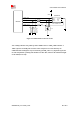
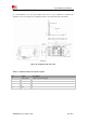
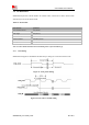
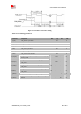
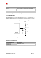
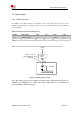
Table Of Contents
- RF Exposure Statement:
- General Notes
- Copyright
- Contents
- Table Index
- Figure Index
- Revision History
- 1Introduction
- 2Package Information
- 3Interface Application
- 3.1Power Supply
- Figure 5: VBAT voltage drop during burst emission
- 3.1.1Power Supply Design Guide
- Figure 6: Power supply application circuit
- Table 7: Recommended Zener diode list
- 3.1.2Recommended Power Supply Circuit
- Figure 7: Linear regulator reference circuit
- Figure 8: Switching mode power supply reference ci
- 3.1.3Voltage Monitor
- 3.2Power on/Power off/Reset Function
- 3.3UART Interface
- 3.4USB Interface
- 3.5USIM Interface
- 3.6PCM Interface
- 3.7SD Interface
- 3.8I2C Interface
- 3.9SDIO Interface
- 3.10SPI Interface
- 3.11Network status
- 3.12Flight Mode Control
- Switch
- 3.1Power Supply
- 4RF Specifications
- 5Electrical Specifications
- 6SMT Production Guide
- 7Packaging
- Appendix

SIM7600SA-H_User Manual_V1.00
2017-10-11
Smart Machine Smart Decision
Figure 19: USIM interface reference circuit
Note: USIM_DATA has been pulled up with a 100KΩ resistor to USIM_VDD in module. A
100nF capacitor on USIM_VDD is used to reduce interference. For more details of AT
commands about USIM, please refer to document [1].USIM_CLK is very important signal, the
rise time and fall time of USIM_CLK should be less than 40ns, otherwise the USIM card might
not be initialized correctly.
Module
VCC
GND
RST
VPP
CLK
I/O
USIM_CLK
USIM_DATA
100nF
USIM Socket
USIM_VDD
USIM_RST
22Ω
22Ω
C707 10M006 512
22Ω
TVS
22pF
_
NM
22pF
_
NM
22pF
_
NM