
User's Manual
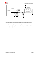
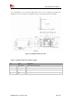
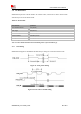
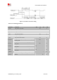
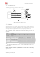
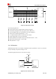
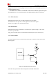
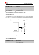
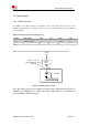
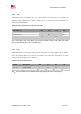
Table Of Contents
- RF Exposure Statement:
- General Notes
- Copyright
- Contents
- Table Index
- Figure Index
- Revision History
- 1Introduction
- 2Package Information
- 3Interface Application
- 3.1Power Supply
- Figure 5: VBAT voltage drop during burst emission
- 3.1.1Power Supply Design Guide
- Figure 6: Power supply application circuit
- Table 7: Recommended Zener diode list
- 3.1.2Recommended Power Supply Circuit
- Figure 7: Linear regulator reference circuit
- Figure 8: Switching mode power supply reference ci
- 3.1.3Voltage Monitor
- 3.2Power on/Power off/Reset Function
- 3.3UART Interface
- 3.4USB Interface
- 3.5USIM Interface
- 3.6PCM Interface
- 3.7SD Interface
- 3.8I2C Interface
- 3.9SDIO Interface
- 3.10SPI Interface
- 3.11Network status
- 3.12Flight Mode Control
- Switch
- 3.1Power Supply
- 4RF Specifications
- 5Electrical Specifications
- 6SMT Production Guide
- 7Packaging
- Appendix

SIM7600SA-H_User Manual_V1.00
2017-10-11
Smart Machine Smart Decision
3.6 PCM Interface
SIM7600SA-H provides a PCM interface for external codec, which can be used in master mode
with short sync and 16 bits linear format.
Table 14: PCM format
Characteristics
Specification
Line Interface Format
Linear(Fixed)
Data length
16bits(Fixed)
PCM Clock/Sync Source
Master Mode(Fixed)
PCM Clock Rate
2048 KHz (Fixed)
PCM Sync Format
Short sync(Fixed)
Data Ordering
MSB
Note: For more details about PCM AT commands, please refer to document [1].
3.6.1 PCM timing
SIM7600SA-H supports 2.048 MHz PCM data and sync timing for 16 bits linear format codec.
Figure 21: PCM_SYNC timing
Figure 22: EXT codec to module timing