
User's Manual
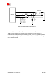
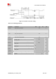
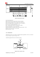
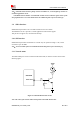
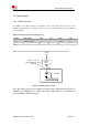
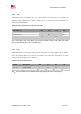
Table Of Contents
- RF Exposure Statement:
- General Notes
- Copyright
- Contents
- Table Index
- Figure Index
- Revision History
- 1Introduction
- 2Package Information
- 3Interface Application
- 3.1Power Supply
- Figure 5: VBAT voltage drop during burst emission
- 3.1.1Power Supply Design Guide
- Figure 6: Power supply application circuit
- Table 7: Recommended Zener diode list
- 3.1.2Recommended Power Supply Circuit
- Figure 7: Linear regulator reference circuit
- Figure 8: Switching mode power supply reference ci
- 3.1.3Voltage Monitor
- 3.2Power on/Power off/Reset Function
- 3.3UART Interface
- 3.4USB Interface
- 3.5USIM Interface
- 3.6PCM Interface
- 3.7SD Interface
- 3.8I2C Interface
- 3.9SDIO Interface
- 3.10SPI Interface
- 3.11Network status
- 3.12Flight Mode Control
- Switch
- 3.1Power Supply
- 4RF Specifications
- 5Electrical Specifications
- 6SMT Production Guide
- 7Packaging
- Appendix

SIM7600SA-H_User Manual_V1.00
2017-10-11
Smart Machine Smart Decision
Table 17: NETLIGHT pin status
NETLIGHT pin status
Module status
Always On
Searching Network; Call Connect(include VOLTE,SRLTE)
200ms ON, 200ms OFF
Data Transmit; 4G registered;
800ms ON, 800ms OFF
2G/3G registered network
OFF
Power off ;Sleep
Note: NETLIGHT output low level as “OFF”, and high level as “ON”.
3.12 Flight Mode Control
The FLIGHTMODE pin can be used to control SIM7600SA-H to enter or exit the Flight mode. In
Flight mode, the RF circuit is closed to prevent interference with other equipments and minimize
current consumption. Bidirectional ESD protection component is suggested to add on
FLIGHTMODE pin, its reference circuit is shown in the following figure.
1.8V
4.7K
FLIGHTMODE
Switch
Module
4.7K
Figure 28: Flight mode switch reference circuit
Table 18: FLIGHTMODE pin status
FLIGHTMODE pin status
Module operation
Input Low Level
Flight Mode: RF is closed
Input High Level
AT+CFUN=0: RF is closed
AT+CFUN=1:RF is working