
User's Manual
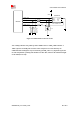
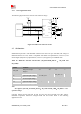
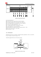
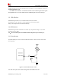
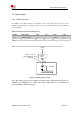
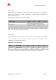
Table Of Contents
- RF Exposure Statement:
- General Notes
- Copyright
- Contents
- Table Index
- Figure Index
- Revision History
- 1Introduction
- 2Package Information
- 3Interface Application
- 3.1Power Supply
- Figure 5: VBAT voltage drop during burst emission
- 3.1.1Power Supply Design Guide
- Figure 6: Power supply application circuit
- Table 7: Recommended Zener diode list
- 3.1.2Recommended Power Supply Circuit
- Figure 7: Linear regulator reference circuit
- Figure 8: Switching mode power supply reference ci
- 3.1.3Voltage Monitor
- 3.2Power on/Power off/Reset Function
- 3.3UART Interface
- 3.4USB Interface
- 3.5USIM Interface
- 3.6PCM Interface
- 3.7SD Interface
- 3.8I2C Interface
- 3.9SDIO Interface
- 3.10SPI Interface
- 3.11Network status
- 3.12Flight Mode Control
- Switch
- 3.1Power Supply
- 4RF Specifications
- 5Electrical Specifications
- 6SMT Production Guide
- 7Packaging
- Appendix

SIM7600SA-H_User Manual_V1.00
2017-10-11
Smart Machine Smart Decision
3.13 Other interface
3.13.1 Sink Current Source
The ISINK pin is VBAT tolerant and intended to drive some passive devices, such as LCD
backlight and white LED, etc. Its output current can be up to 40mA and be set by the AT command
“AT+ CLEDITST”.
Table 19: Sink current electronic characteristic
Symbol
Description
Min.
Typ.
Max.
Unit
V
ISINK
Voltage tolerant
0.5
-
VBAT
V
I
ISINK
Current tolerant
0
-
40
mA
ISINK is a ground-referenced current sink. The following figure shows its reference circuit.
VBAT
ISINK pin is VBAT
tolerant-suitable for driving
white LEDs
+
Passive
device
-
ISINK
MODULE
Current Controls
Figure 29: ISINK reference circuit
Note: The sinking current can be adjusted to meet the design requirement through the AT
command “AT+ CLEDITST =<0>, <value>”.The “value” ranges from 0 to 8, on behalf of the
current from 0mA to 40mA by 5mA step.