
User's Manual
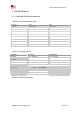
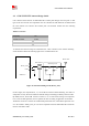
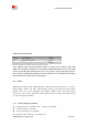
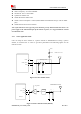

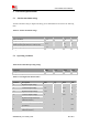
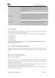
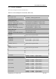
Table Of Contents
- RF Exposure Statement:
- General Notes
- Copyright
- Contents
- Table Index
- Figure Index
- Revision History
- 1Introduction
- 2Package Information
- 3Interface Application
- 3.1Power Supply
- Figure 5: VBAT voltage drop during burst emission
- 3.1.1Power Supply Design Guide
- Figure 6: Power supply application circuit
- Table 7: Recommended Zener diode list
- 3.1.2Recommended Power Supply Circuit
- Figure 7: Linear regulator reference circuit
- Figure 8: Switching mode power supply reference ci
- 3.1.3Voltage Monitor
- 3.2Power on/Power off/Reset Function
- 3.3UART Interface
- 3.4USB Interface
- 3.5USIM Interface
- 3.6PCM Interface
- 3.7SD Interface
- 3.8I2C Interface
- 3.9SDIO Interface
- 3.10SPI Interface
- 3.11Network status
- 3.12Flight Mode Control
- Switch
- 3.1Power Supply
- 4RF Specifications
- 5Electrical Specifications
- 6SMT Production Guide
- 7Packaging
- Appendix

SIM7600SA-H_User Manual_V1.00
2017-10-11
Smart Machine Smart Decision
4.2 GSM /UMTS/LTE Antenna Design Guide
Users should connect antennas to SIM7600SA-H’s antenna pads through micro-strip line or other
types of RF trace and the trace impedance must be controlled in 50Ω. SIMCom recommends that
the total insertion loss between the antenna pads and antennas should meet the following
requirements:
Table 27: Trace loss
Frequency
Loss
700MHz-960MHz
<0.5dB
1710MHz-2170MHz
<0.9dB
2300MHz-2650MHz
<1.2dB
To facilitate the antenna tuning and certification test, a RF connector and an antenna matching
circuit should be added. The following figure is the recommended circuit.
MAIN ANT
RF connector
Matching circuit
82
R1
41
C1
R2
C2
D1
Figure 30: Antenna matching circuit (MAIN_ANT)
In above figure, the components R1, C1, C2 and R2 are used for antenna matching, the values of
components can only be achieved after the antenna tuning and usually provided by antenna vendor.
By default, the R1, R2 are 0Ω resistors, and the C1, C2 are reserved for tuning. The component
D1 is a TVS for ESD protection, and it is optional for users according to application environment.
The RF test connector is used for the conducted RF performance test, and should be placed as close
as to the module’s MAIN_ANT pin. The traces impedance between SIM7600SA-H and antenna
must be controlled in 50Ω .
MAIN_ANT
GND
MODULE