
User's Manual
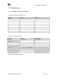
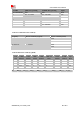
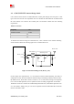
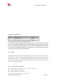
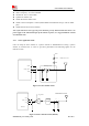

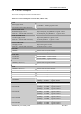
Table Of Contents
- RF Exposure Statement:
- General Notes
- Copyright
- Contents
- Table Index
- Figure Index
- Revision History
- 1Introduction
- 2Package Information
- 3Interface Application
- 3.1Power Supply
- Figure 5: VBAT voltage drop during burst emission
- 3.1.1Power Supply Design Guide
- Figure 6: Power supply application circuit
- Table 7: Recommended Zener diode list
- 3.1.2Recommended Power Supply Circuit
- Figure 7: Linear regulator reference circuit
- Figure 8: Switching mode power supply reference ci
- 3.1.3Voltage Monitor
- 3.2Power on/Power off/Reset Function
- 3.3UART Interface
- 3.4USB Interface
- 3.5USIM Interface
- 3.6PCM Interface
- 3.7SD Interface
- 3.8I2C Interface
- 3.9SDIO Interface
- 3.10SPI Interface
- 3.11Network status
- 3.12Flight Mode Control
- Switch
- 3.1Power Supply
- 4RF Specifications
- 5Electrical Specifications
- 6SMT Production Guide
- 7Packaging
- Appendix

SIM7600SA-H_User Manual_V1.00
2017-10-11
Smart Machine Smart Decision
Receiver Type: 16-channel, C/A Code
GPS L1 Frequency: 1575.42±1.023MHz
GLONASS: 1597.5~1605.8 MHz
Update rate: Default 1 Hz
GNSS data format: NMEA-0183
GNSS Current consumption : 100mA (GSM/CDMA 1X/UMTS/LTE Sleep ,in total on VBAT
pins)
GNSS antenna: Passive/Active antenna
Note: If the antenna is active type, the power should be given by main board because there is no
power supply on the GPS antenna pad. If the antenna is passive, it is suggested that the external
LNA should be used.
4.3.2 GNSS Application Guide
Users can adopt an active antenna or a passive antenna to SIM7600SA-H. If using a passive
antenna, an external LNA is a must to get better performance. The following figures are the
reference circuits.
VDD
10 ohm
GNSS Active ANT
47nH
Matching circuit
L1
L2
Figure 32: Active antenna circuit
GND
GNSS_ANT
GND
MODULE
SAW
V_LNA
GNSS Passive ANT
80
Matching circuit
C1
79
LNA
L3
78
L1
L2
Figure 33: Passive antenna circuit (Default)
GND
80
GNSS_ANT
79
GND 78
MODULE