
User's Manual
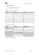
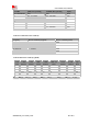
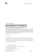
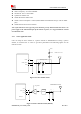

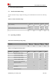
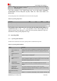
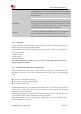
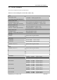
Table Of Contents
- RF Exposure Statement:
- General Notes
- Copyright
- Contents
- Table Index
- Figure Index
- Revision History
- 1Introduction
- 2Package Information
- 3Interface Application
- 3.1Power Supply
- Figure 5: VBAT voltage drop during burst emission
- 3.1.1Power Supply Design Guide
- Figure 6: Power supply application circuit
- Table 7: Recommended Zener diode list
- 3.1.2Recommended Power Supply Circuit
- Figure 7: Linear regulator reference circuit
- Figure 8: Switching mode power supply reference ci
- 3.1.3Voltage Monitor
- 3.2Power on/Power off/Reset Function
- 3.3UART Interface
- 3.4USB Interface
- 3.5USIM Interface
- 3.6PCM Interface
- 3.7SD Interface
- 3.8I2C Interface
- 3.9SDIO Interface
- 3.10SPI Interface
- 3.11Network status
- 3.12Flight Mode Control
- Switch
- 3.1Power Supply
- 4RF Specifications
- 5Electrical Specifications
- 6SMT Production Guide
- 7Packaging
- Appendix

SIM7600SA-H_User Manual_V1.00
2017-10-11
Smart Machine Smart Decision
I
IL
Input low leakage current(no
pull up resistor)
-1
-
-
uA
*Note: These parameters are for digital interface pins, such as SPI, GPIOs (NETLIGHT,
FLIGHTMODE, STATUS, USIM_DET, SD_DET), SDIO, I2C, UART, PCM, COEXn, and
BOOT_CFG0.
The operating temperature of SIM7600SA-H is listed in the following table.
Table 32: Operating temperature
Parameter
Min.
Typ.
Max.
Unit
Normal operation temperature
-30
25
80
℃
Extended operation temperature*
-40
25
85
℃
Storage temperature
-45
25
+90
℃
*Note: Module is able to make and receive voice calls, data calls, SMS and make GSM/CDMA
1X/UMTX/LTE traffic in -40℃ ~ +85℃. The performance will be reduced slightly from the
3GPP specifications if the temperature is outside the normal operating temperature range and
still within the extreme operating temperature range.
5.3 Operating Mode
5.3.1 Operating Mode Definition
The table below summarizes the various operating modes of SIM7600SA-H product.
Table 33: Operating mode Definition
Mode
Function
Normal operation
GSM /UMTS/LTE
Sleep
In this case, the current consumption of module will be reduced to the
minimal level and the module can still receive paging message and
SMS.
GSM/UMTS/LTE
Idle
Software is active. Module is registered to the network, and the
module is ready to communicate.
GSM/UMTS/LTE
Talk
Connection between two subscribers is in progress. In this case, the
power consumption depends on network settings such as DTX off/on,
FR/EFR/HR, hopping sequences, and antenna.
GPRS/EDGE/
UMTS/LTE Standby
Module is ready for data transmission, but no data is currently sent or
received. In this case, power consumption depends on network
settings.
GPRS/EDGE/
UMTS/LTE
Data transmission
There is data transmission in progress. In this case, power
consumption is related to network settings (e.g. power control level);
uplink/downlink data rates, etc.
Minimum functionality
mode
AT command “AT+CFUN=0” AT+CSCLK=1 can be used to set the
module to a minimum functionality mode without removing the