
User's Manual

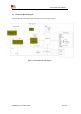
Table Of Contents
- RF Exposure Statement:
- General Notes
- Copyright
- Contents
- Table Index
- Figure Index
- Revision History
- 1Introduction
- 2Package Information
- 3Interface Application
- 3.1Power Supply
- Figure 5: VBAT voltage drop during burst emission
- 3.1.1Power Supply Design Guide
- Figure 6: Power supply application circuit
- Table 7: Recommended Zener diode list
- 3.1.2Recommended Power Supply Circuit
- Figure 7: Linear regulator reference circuit
- Figure 8: Switching mode power supply reference ci
- 3.1.3Voltage Monitor
- 3.2Power on/Power off/Reset Function
- 3.3UART Interface
- 3.4USB Interface
- 3.5USIM Interface
- 3.6PCM Interface
- 3.7SD Interface
- 3.8I2C Interface
- 3.9SDIO Interface
- 3.10SPI Interface
- 3.11Network status
- 3.12Flight Mode Control
- Switch
- 3.1Power Supply
- 4RF Specifications
- 5Electrical Specifications
- 6SMT Production Guide
- 7Packaging
- Appendix

Smart Machine Smart Decision
SIM7600SA-H_User Manual_V1.00
2017-10-11
Table Index
Table 1: SIM7600SA-H frequency bands...............................................................................................................8
Table 2: General features...................................................................................................................................... 11
Table 3: Pin definition.......................................................................................................................................... 14
Table 4: IO parameters definition......................................................................................................................... 15
Table 5: Pin description........................................................................................................................................ 15
Table 6: VBAT pins electronic characteristic........................................................................................................21
Table 7: Recommended Zener diode list...............................................................................................................22
Table 8: Power on timing and electronic characteristic........................................................................................ 25
Table 9: Power off timing and electronic characteristic........................................................................................ 26
Table 10: RESET pin electronic characteristic......................................................................................................27
Table 11: USIM electronic characteristic in 1.8V mode (USIM_VDD=1.8V)..................................................... 30
Table 12: USIM electronic characteristic 3.0V mode (USIM_VDD=2.95V).......................................................30
Table 13: Amphenol USIM socket pin description............................................................................................... 32
Table 14: PCM format.......................................................................................................................................... 33
Table 15: PCM timing parameters........................................................................................................................ 34
Table 16: MMC/SD electronic characteristic (SD_DATA0-SD_DATA3,SD_CLK and SD_CMD) *..............35
Table 17: NETLIGHT pin status.......................................................................................................................... 38
Table 18: FLIGHTMODE pin status.................................................................................................................... 38
Table 19: Sink current electronic characteristic.................................................................................................... 39
Table 20: ADC1 and ADC2 electronic characteristics.......................................................................................... 40
Table 21: Electronic characteristic........................................................................................................................ 40
Table 22: Conducted transmission power............................................................................................................. 41
Table 23: Operating frequencies...........................................................................................................................41
Table 24: E-UTRA operating bands..................................................................................................................... 41
Table 25: Conducted receive sensitivity............................................................................................................... 42
Table 26: Reference sensitivity (QPSK)............................................................................................................... 42
Table 27: Trace loss.............................................................................................................................................. 44
Table 28: Recommended TVS..............................................................................................................................45
Table 29: Absolute maximum ratings................................................................................................................... 48
Table 30: Recommended operating ratings...........................................................................................................48
Table 31: 1.8V Digital I/O characteristics*...........................................................................................................48
Table 32: Operating temperature.......................................................................................................................... 49
Table 33: Operating mode Definition................................................................................................................... 49
Table 34: Current consumption on VBAT Pins (VBAT=3.8V)............................................................................ 51
Table 35: The ESD performance measurement table (Temperature: 25
℃
, Humidity: 45%)................................52
Table 37: Moisture Sensitivity Level and Floor Life............................................................................................ 53
Table 38: Tray size................................................................................................................................................56
Table 39: Small Carton size..................................................................................................................................56
Table 40: Big Carton size......................................................................................................................................56
Table 41: Coding Schemes and Maximum Net Data Rates over Air Interface..................................................... 57
Table 42: Related Documents...............................................................................................................................60
Table 43: Terms and Abbreviations...................................................................................................................... 62
Table 44: Safety Caution...................................................................................................................................... 64