
User's Manual

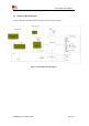
Table Of Contents
- RF Exposure Statement:
- General Notes
- Copyright
- Contents
- Table Index
- Figure Index
- Revision History
- 1Introduction
- 2Package Information
- 3Interface Application
- 3.1Power Supply
- Figure 5: VBAT voltage drop during burst emission
- 3.1.1Power Supply Design Guide
- Figure 6: Power supply application circuit
- Table 7: Recommended Zener diode list
- 3.1.2Recommended Power Supply Circuit
- Figure 7: Linear regulator reference circuit
- Figure 8: Switching mode power supply reference ci
- 3.1.3Voltage Monitor
- 3.2Power on/Power off/Reset Function
- 3.3UART Interface
- 3.4USB Interface
- 3.5USIM Interface
- 3.6PCM Interface
- 3.7SD Interface
- 3.8I2C Interface
- 3.9SDIO Interface
- 3.10SPI Interface
- 3.11Network status
- 3.12Flight Mode Control
- Switch
- 3.1Power Supply
- 4RF Specifications
- 5Electrical Specifications
- 6SMT Production Guide
- 7Packaging
- Appendix

Smart Machine Smart Decision
SIM7600SA-H_User Manual_V1.00
2017-10-11
Figure Index
Figure 1: SIM7600SA-H block diagram...............................................................................................................10
Figure 2: Pin assignment overview....................................................................................................................... 13
Figure 3: Dimensions (Unit: mm)......................................................................................................................... 19
Figure 4: Footprint recommendation (Unit: mm).................................................................................................. 20
Figure 5: VBAT voltage drop during burst emission (GSM/GPRS)...................................................................... 21
Figure 6: Power supply application circuit............................................................................................................22
Figure 7: Linear regulator reference circuit........................................................................................................... 23
Figure 8: Switching mode power supply reference circuit.....................................................................................23
Figure 9: Reference power on/off circuit...............................................................................................................24
Figure 10: Power on timing sequence................................................................................................................... 24
Figure 11: Power off timing sequence...................................................................................................................25
Figure 12: Reference reset circuit..........................................................................................................................26
Figure 13: UART full modem............................................................................................................................... 27
Figure 14: UART null modem.............................................................................................................................. 27
Figure 15: Reference circuit of level shift............................................................................................................. 28
Figure 16: RI behaviour(SMS and URC report).............................................................................................. 28
Figure 17: RI behaviour
(
voice call
)
................................................................................................................. 29
Figure 18: USB reference circuit...........................................................................................................................29
Figure 19: USIM interface reference circuit..........................................................................................................31
Figure 20: Amphenol SIM card socket..................................................................................................................32
Figure 21: PCM_SYNC timing.............................................................................................................................33
Figure 22: EXT codec to module timing............................................................................................................... 33
Figure 23: Module to EXT codec timing...............................................................................................................34
Figure 24: Audio codec reference circuit...............................................................................................................35
Figure 25: SD reference circuit............................................................................................................................. 36
Figure 26: I2C reference circuit............................................................................................................................ 36
Figure 27: NETLIGHT reference circuit...............................................................................................................37
Figure 28: Flight mode switch reference circuit.................................................................................................... 38
Figure 29: ISINK reference circuit........................................................................................................................ 39
Figure 30: Antenna matching circuit (MAIN_ANT)............................................................................................. 44
Figure 31: Antenna matching circuit (AUX_ANT)............................................................................................... 45
Figure 32: Active antenna circuit.......................................................................................................................... 46
Figure 33: Passive antenna circuit (Default)..........................................................................................................46
Figure 36: The ramp-soak-spike reflow profile of SIM7600SA-H........................................................................53
Figure 37: packaging diagram...............................................................................................................................55
Figure 38: Tray drawing........................................................................................................................................55
Figure 39: Small carton drawing...........................................................................................................................56
Figure 40: Big carton drawing...............................................................................................................................56