
Users Manual Part 2


SIM8260A_Hardware Design_V1.05
www.simcom.com 53 / 122
After inserting (U)SIM card, the (U)SIM_DET pin will change from low to high level. The rising edge will
indicate that the (U)SIM card has been inserted. After removing the (U)SIM card, the (U)SIM_DET pin will
change from high to low level. This falling edge will indicate the removal of the (U)SIM card.
Using “AT+UIMHOTSWAPON=0 or 1” and “AT+UIMHOTSWAPLEVEL=0 or 1”AT command to set module
SIM card hot swap function enable and SIM card detection level, for more details, please refer to SIM8200
Series_AT Command Manual document.
Using “AT+SMSIMCFG=1,1” and “AT+SMSIMCFG=1,2” AT command to switch (U)SIM1 and (U)SIM2
function, for more details, please refer to SIM8200 Series_AT Command Manual document.
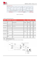
Table 32: Definition of (U)SIM interface
Pin name
Pin
no.
Pin
characteristics
Functional description
Comment
(U)SIM1_VDD
B51
PO
P4
Power supply for (U)SIM1 card
1.8/3.0V voltage
domain, (U)SIM
interface should
be protected
against ESD.
If unused, please
keep open
(U)SIM1_DATA
E51
DIO
P4
(U)SIM1 card data signal, which
has been pulled up to
(U)SIM1_VDD by a 20K resistor
internally
(U)SIM1_CLK
D49
DO
P4
(U)SIM1 clock signal
(U)SIM1_RST
C51
DO
P4
(U)SIM1 reset signal
(U)SIM1_DET
E47
DI
P3
(U)SIM1 card detect signal,
which need pulled up to
VDD_EXT by a 470K resistor
externally
(U)SIM2_VDD
F49
PO
P5
Power supply for (U)SIM2 card
(U)SIM2_DATA
G47
DIO
P5
(U)SIM2 card data, which has
been pulled up to (U)SIM2_VDD
by a 20K resistor internally
(U)SIM2_CLK
H49
DO
P5
(U)SIM2 clock signal
(U)SIM2_RST
G51
DO
P5
(U)SIM2 reset signal
(U)SIM2_DET
F45
DI
P3
(U)SIM2 card detect, which need
pulled up to VDD_EXT by a
470KR resistor externally
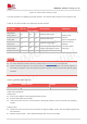
The following table shows recommended TVS of ESD protect and (U)SIM socket.
Table 33: Recommended TVS and (U)SIM socket list
Name
Manufacturer
Model
TVS
ST
ESDA6V1-5W6
(U)SIM socket
Suntech
5039600696