
Users Manual Part 2


SIM8260A_Hardware Design_V1.05
www.simcom.com 54 / 122
If the (U)SIM card hot-swap function is not used, customers should keep the (U)SIM_DET pin open.
The (U)SIM card layout guidelines:
Make sure that the (U)SIM card socket should be far away from the antennas.
(U)SIM traces should be away from RF, VBAT and high-speed signals.
The traces should be as short as possible.
Keep (U)SIM socket’s GND pin directly connect to the main ground.
Shielding the (U)SIM card signals by ground.
Recommended to place a 33pF~1uF capacitor on (U)SIM_VDD net and place close to the
holder.
The rise/fall time of (U)SIM_CLK should not exceed 40ns.
The parasitic capacitance of TVS should not exceed 60pF, and the TVS should be placed close
to the (U)SIM socket.
3.9 I2S Interface
SIM8260A supports one I2S/PCM interface for external codec, which meets the requirements in the
Phillips I2S bus specification.
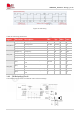
Table 34: I2S format
For more details about I2S AT commands, please refer to document [1] in the appendix.
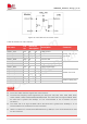
3.9.1 I2S Timing
The module supports I2S sampling rate of 48 KHz and 32bit coding signal (16bit length), the timing
sequence is shown in the following figure.
Characteristics
Specification
Line interface format
Linear(fixed)
Data length
16bits(fixed)
I2S flock/sync source
Master mode(fixed)
I2S clock sate
1.536 MHz (default)
I2S MCLK rate
12.288MHz (default)
Data ordering
MSB
NOTE