
Hardware Design V1.00
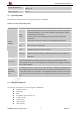


Table Of Contents
- Version History
- 1. Introduction
- 2. SIM2000S Overview
- 3. Package Information
- 4. Application Interface
- 4.1. Power Supply
- 4.2. Power on/down Scenarios
- 4.3. Power Saving Mode
- 4.4. Serial Port and Debug Interface
- 4.5. RI behaviors
- 4.6. Audio Interfaces
- 4.7. RUIM Card Interface
- 4.8. PCM Interface
- 4.9. Keypad Interface
- 4.10. I2C Bus
- 4.11. General Purpose Input/Output (GPIO)
- 4.12. ADC
- 4.13. PWM
- 4.14. Network Status Indication
- 4.15. NETLIGHT Multiplexing Function
- 4.16. Operating Status Indication
- 4.17. Antenna Interface
- 5. PCB Layout
- 6. Electrical, Reliability and Radio Characteristics
- 7. Manufacturing
- 8. Appendix

Smart Machine Smart Decision
SIM2000S_Hardware_Design_V1.00 14 2014-02-27
Power supply
VBAT 55,56,57 I 3.4~4.4 Power supply
VDD_EXT 15 O 2.85
2.85V output power
supply
If it is unused, keep
open.
GND
2,17,18,29,39,
45,46,53,54,
58,59,61,62,
63,64,65
Ground
Power on/down
PWRKEY 1 I 1.8
PWRKEY should be
pulled low at least 1
second and then released
to power on/down the
module.
Pulled up internally.
Audio interfaces
MICP 19
MICN 20
I
Differential audio input
SPKP 21
SPKN 22
O
Differential audio output
If these pins are unused,
keep open.
Status
STATUS 66 O 2.85 Power on status
NETLIGHT 52 O 1.8 Network status
If these pins are unused,
keep open.
PCM interface
PCMCLK
11 O
PCMIN
12 I
PCMOUT
13 O
PCMSYNC
14 O
1.8 PCM interface
If these pins are unused,
keep open.
USB interface
VBUS 6 I 4.4~5.5
USB_DP 23 I/O
USB_DM 24 I/O
Debug and download
If these pins are unused,
keep open.
I
2
C interface
SDA 37 I/O I2C serial bus data
SCL 38 O
1.8
I2C serial bus clock
If these pins are unused,
keep open.
Debug interface
DEBUG_TXD 27 O
DEBUG_RXD 28 I
2.8 Debug
If these pins are unused,
keep open.
Keypad interface
KBR0 44 keypad row 0
KBR1 43 keypad row 1
KBR2 42 keypad row 2
KBR3 41 keypad row 3
KBR4 40
I/O 1.8
keypad row 4
If these pins are unused,
keep open.