
Hardware Design V1.00
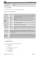


Table Of Contents
- Version History
- 1. Introduction
- 2. SIM2000S Overview
- 3. Package Information
- 4. Application Interface
- 4.1. Power Supply
- 4.2. Power on/down Scenarios
- 4.3. Power Saving Mode
- 4.4. Serial Port and Debug Interface
- 4.5. RI behaviors
- 4.6. Audio Interfaces
- 4.7. RUIM Card Interface
- 4.8. PCM Interface
- 4.9. Keypad Interface
- 4.10. I2C Bus
- 4.11. General Purpose Input/Output (GPIO)
- 4.12. ADC
- 4.13. PWM
- 4.14. Network Status Indication
- 4.15. NETLIGHT Multiplexing Function
- 4.16. Operating Status Indication
- 4.17. Antenna Interface
- 5. PCB Layout
- 6. Electrical, Reliability and Radio Characteristics
- 7. Manufacturing
- 8. Appendix

Smart Machine Smart Decision
SIM2000S_Hardware_Design_V1.00 15 2014-02-27
KBC0 51 keypad column 1
KBC1 50 keypad column 1
KBC2 49 keypad column 2
KBC3 48 keypad column 3
KBC4 47 keypad column 4
GPIO33 67 GPIO33
GPIO34 68
I/O 1.8
GPIO34
Serial port
RXD 10 I Receive data
TXD 9 O Transmit data
RTS 8 I Request to send
CTS 7 O Clear to send
DCD 5 O Data carrier detect
RI 4 O Ring indicator
DTR 3 I
2.85
Data terminal ready
If these pins are unused,
keep open.
RUIM interface
RUIM_VDD 30 O
Voltage supply for
RUIM card. Support
1.8V or 3V RUIM card
RUIM_DATA 31 I/O RUIM data input/output
RUIM_CLK 32 O RUIM clock
RUIM_RST 33 O
1.8/3
RUIM reset
All signals of RUIM
interface should be
protected against ESD
with a TVS diode array.
RUIM_PRESENCE 34 I 1.8 RUIM card detection
If it is unused, keep
open.
ADC
ADC1 25 I
Input voltage range: 0V
~ 2.5V
ADC2 36 I
Input voltage range: 0V
~ 2.5V
If it is unused, keep
open.
External reset
RESET 16 I 1.8 Reset input(Active low)
Recommend connecting
a 100nF capacitor.
Pulse width modulation( PWM )
PWM 35 O 2.85 PWM
If these pins are unused,
keep open.
RF interface
RF_ANT 60 I/O
Radio antenna
connection
Impendence must be
controlled to 50.
Not connect
NC 26
These pins should be
kept open.