
Hardware Design V1.00
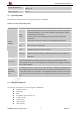


Table Of Contents
- Version History
- 1. Introduction
- 2. SIM2000S Overview
- 3. Package Information
- 4. Application Interface
- 4.1. Power Supply
- 4.2. Power on/down Scenarios
- 4.3. Power Saving Mode
- 4.4. Serial Port and Debug Interface
- 4.5. RI behaviors
- 4.6. Audio Interfaces
- 4.7. RUIM Card Interface
- 4.8. PCM Interface
- 4.9. Keypad Interface
- 4.10. I2C Bus
- 4.11. General Purpose Input/Output (GPIO)
- 4.12. ADC
- 4.13. PWM
- 4.14. Network Status Indication
- 4.15. NETLIGHT Multiplexing Function
- 4.16. Operating Status Indication
- 4.17. Antenna Interface
- 5. PCB Layout
- 6. Electrical, Reliability and Radio Characteristics
- 7. Manufacturing
- 8. Appendix

Smart Machine Smart Decision
4. Application Interface
4.1. Power Supply
The power supply range of SIM2000S is from 3.4V to 4.4V. Recommended voltage is 3.8V. The power supply
must be able to provide sufficient current up to 600mA. For the VBAT input, a bypass capacitor (low ESR) such
as a 100 µF is strongly recommended.
A 5.1V/500mW Zener diode is strongly recommended, the diode can prevent chip from damaging by the
voltage surge. These capacitors and Zener diode should be placed as close as possible to SIM2000S VBAT
pins.
Figure 5: Reference circuit of the VBAT input
Table 4: Recommended Zener diode
Vendor Part number Power(watts) Packages
1 On semi MMSZ5231BT1G 500mW SOD123
2 Prisemi PZ3D4V2H 500mW SOD323
3 Prisemi PZ5D4V2H 500mW SOD523
4 Vishay MMSZ4689-V 500mW SOD123
5 Crownpo CDZ55C5V1SM 500mW 0805
The following figure is the reference design of +5V input power supply. The designed output for the power
supply is 4V, thus a linear regulator can be used.
Figure 6: Reference circuit of the LDO power supply
SIM2000S_Hardware_Design_V1.00 18 2014-02-27