
Hardware Design V1.00


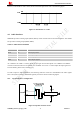
Table Of Contents
- Version History
- 1. Introduction
- 2. SIM2000S Overview
- 3. Package Information
- 4. Application Interface
- 4.1. Power Supply
- 4.2. Power on/down Scenarios
- 4.3. Power Saving Mode
- 4.4. Serial Port and Debug Interface
- 4.5. RI behaviors
- 4.6. Audio Interfaces
- 4.7. RUIM Card Interface
- 4.8. PCM Interface
- 4.9. Keypad Interface
- 4.10. I2C Bus
- 4.11. General Purpose Input/Output (GPIO)
- 4.12. ADC
- 4.13. PWM
- 4.14. Network Status Indication
- 4.15. NETLIGHT Multiplexing Function
- 4.16. Operating Status Indication
- 4.17. Antenna Interface
- 5. PCB Layout
- 6. Electrical, Reliability and Radio Characteristics
- 7. Manufacturing
- 8. Appendix

Smart Machine Smart Decision
Figure 16: Level matching circuit
4.4.3 USB Interface
SIM2000S could achieve software debug function through USB interface. When powering on the module,
connecting VBUS, USB_DP, USB_DM, and GND to PC, then installing the driver following the prompts, a USB
port could be recognized by PC, customer could achieve the software Debug with USB port.
SIMCom
recommendeds the following connection figure:
SIM2000S_Hardware_Design_V1.00 27 2014-02-27
Figure 17: USB reference circuit
The TVS on USB data line should be less than 5pf, and traced by differential forms
Note: please reserve the USB interface or test point for further debugging
22R
USB_DM
MODULE
22R
USB_DP
VBUS
1uF
USB_DM
USB_DP
VBUS
GNDGND
USB
VBUS