
Hardware Design V1.00


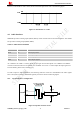
Table Of Contents
- Version History
- 1. Introduction
- 2. SIM2000S Overview
- 3. Package Information
- 4. Application Interface
- 4.1. Power Supply
- 4.2. Power on/down Scenarios
- 4.3. Power Saving Mode
- 4.4. Serial Port and Debug Interface
- 4.5. RI behaviors
- 4.6. Audio Interfaces
- 4.7. RUIM Card Interface
- 4.8. PCM Interface
- 4.9. Keypad Interface
- 4.10. I2C Bus
- 4.11. General Purpose Input/Output (GPIO)
- 4.12. ADC
- 4.13. PWM
- 4.14. Network Status Indication
- 4.15. NETLIGHT Multiplexing Function
- 4.16. Operating Status Indication
- 4.17. Antenna Interface
- 5. PCB Layout
- 6. Electrical, Reliability and Radio Characteristics
- 7. Manufacturing
- 8. Appendix

Smart Machine Smart Decision
State RI response
Standby High
Voice call
The pin is changed to low. When any of the following events occurs, the pin will be changed
to high:
(1)Establish the call
(2)Hang up the call
Data call
The pin is changed to low. When any of the following events occurs, the pin will be changed
to high:
(1)Establish the call
(2)Hang up the call
SMS
The pin is changed to low, and kept low for 120ms when a SMS is received. Then it is
changed to high.
URC
The pin is changed to low, and kept low for 120ms when some URCs are reported. Then it is
changed to high. For more details, please refer to document [10].
The behavior of the RI pin is shown in the following figure when the module is used as a receiver.
HIGH
LOW
Idle Ring
Hang up the call
Establish the call
RI
Figure 18: RI behaviour of voice calling as a receiver
Figure 19: RI behaviour of data calling as a receiver
Figure 20: RI behaviour of URC or receive SMS
SIM2000S_Hardware_Design_V1.00 29 2014-02-27